Stall protection device for vertical elevator

A protection device, vertical lifting technology, used in elevators, transportation and packaging, etc., can solve problems such as the impact of goods, and achieve the effect of avoiding safety problems and increasing friction.

Inactive Publication Date: 2022-06-24
广东鑫奥电梯有限公司
View PDF1 Cites 0 Cited by
  • Summary
  • Abstract
  • Description
  • Claims
  • Application Information

AI Technical Summary

Problems solved by technology

[0003] At present, a Chinese patent CN108249251B discloses a kind of anti-fall protection device for vertical lift elevators. The non-elastic sections of the two pull ropes are wound in the first double helical groove and the second double helical groove through the screw rod, and the rotation The cantilever stretches the elastic section, and then uses the suspension cable to limit the cantilever to prevent torsion. When the elevator is running normally, the suspension cable is in a straightened state under the tension of the steel wire rope. When the steel wire rope breaks, the car falls and the suspension cable is not affected. At this time, the elastic section of the pull rope shrinks, driving the screw rod to rotate, thereby driving the rotary disc to rotate, squeezing the roller, and the limit cross brace guide sleeve extends outside, and is used in conjunction with the anti-fall block on the side wall of the elevator shaft to avoid The car continues to fall, so as to achieve anti-fall protection, but when the van elevator stalls up or down, there will be acceleration. If it descends rapidly, the limit cross brace will contact the anti-fall block, which will cause the van elevator to stop suddenly. Generate a huge impact, which will affect the people or goods in the elevator

Method used


Image

  • Stall protection device for vertical elevator
  • Stall protection device for vertical elevator
  • Stall protection device for vertical elevator

Examples


Embodiment 1

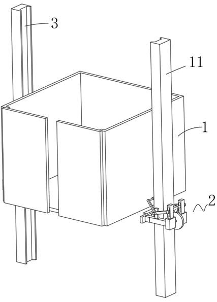
[0028] like figure 1 and Figure 4 and Figure 5 , the present invention provides a stall protection device for a vertical lift elevator, comprising a car body 1 and two guide rail plates 11 with a guiding function, and a deceleration mechanism 2 is sleeved on the guide rail plates 11;

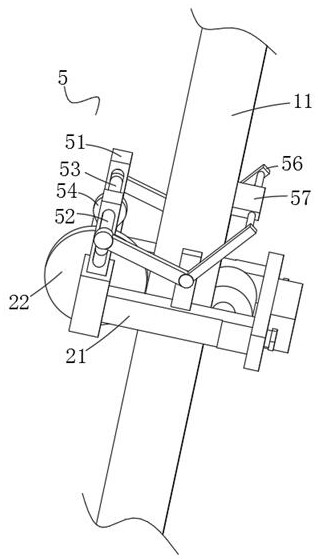
[0029] The deceleration mechanism 2 includes a connecting rod 21 slidably connected to both sides of the guide rail plate 11 . The outer side of the connecting rod 21 is provided with a rotating wheel 22 that rotates on the side wall of the guide rail plate 11 , and the two sides of the rotating wheel 22 are coaxially connected with a rotating shaft. 23. The rotating shaft 23 extends to the interior of the connecting rod 21 and is connected with a stall sensing device 24. The interior of the connecting rod 21 is provided with a telescopic rod 25 that is electrically connected to the stall sensing device 24, and a friction wheel 26 is rotatably connected to the interior of the connecting rod 2...

Embodiment 2

[0036] like figure 1 and figure 2 and image 3 , a stall protection device for a vertical lift elevator, comprising a car body 1 and two guide rail plates 11 with a guiding function, and a deceleration mechanism 2 is sleeved on the guide rail plates 11;

[0037] The deceleration mechanism 2 includes a connecting rod 21 slidably connected to both sides of the guide rail plate 11 . The outer side of the connecting rod 21 is provided with a rotating wheel 22 that rotates on the side wall of the guide rail plate 11 , and the two sides of the rotating wheel 22 are coaxially connected with a rotating shaft. 23. The rotating shaft 23 extends to the interior of the connecting rod 21 and is connected with a stall sensing device 24. The interior of the connecting rod 21 is provided with a telescopic rod 25 that is electrically connected to the stall sensing device 24, and a friction wheel 26 is rotatably connected to the interior of the connecting rod 21. The friction wheel 26 is pro...

Embodiment 3

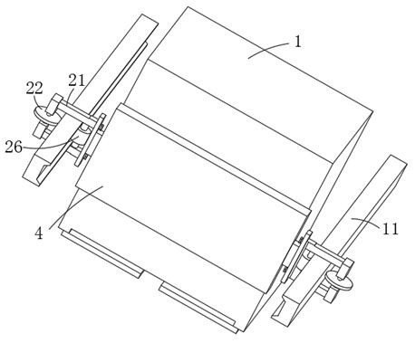
[0042] like Figure 1 to Figure 5 , a stall protection device for a vertical lift elevator, comprising a car body 1 and two guide rail plates 11 with a guiding function, the front end of the car body 1 is provided with an opening, the opening is slidably connected with a door plate, and the guide rail plate 11 is sleeved The deceleration mechanism 2 is connected, and the opposite surfaces of the two deceleration mechanisms 2 are bolted with support plates 4. The car body 1 is fixedly installed above the support plate 4, and the car body 1 is placed on the support plate 4, which can increase the capacity of the car body 1. stability,

[0043] The deceleration mechanism 2 includes a connecting rod 21 slidably connected to both sides of the guide rail plate 11 . The outer side of the connecting rod 21 is provided with a rotating wheel 22 that rotates on the side wall of the guide rail plate 11 , and the two sides of the rotating wheel 22 are coaxially connected with a rotating sh...


PUM


Abstract

The invention relates to the technical field of elevator use, and discloses a stall protection device for a vertical lifting elevator, which comprises a car body and two guide rail plates with a guiding function, and the guide rail plates are sleeved with speed reducing mechanisms; the speed reducing mechanism comprises connecting rods connected to the two sides of the guide rail plate in a sliding mode, and rotating wheels rotating on the side wall of the guide rail plate are arranged on the outer sides of the connecting rods. According to the protection device, when the compartment body stalls, the compartment body and the whole speed reducing mechanism can quickly move on the guide rail plate, the rotating wheels can rotate on the outer wall of the guide rail plate, the rotating speed can be increased, the stall sensing device works under the action of the rotating shaft when the speed reaches a set value, the telescopic rod is started to work, and the telescopic rod can be inserted into the limiting hole, so that the stall is prevented from being damaged. Therefore, the friction wheel stops rotating, the friction wheel and the wedge-shaped groove are in sliding connection instead of rotating connection, friction force is increased, the speed reduction effect can be achieved, and the safety problem caused by stall is effectively avoided.

Description

technical field [0001] The invention relates to the technical field of elevator use, in particular to a stall protection device for a vertical lift elevator. Background technique [0002] Elevators are widely used in various multi-storey buildings. According to their movement methods, they can be divided into vertical lift type, step type and crawler type. In modern high-rise buildings, vertical lift elevators are mostly used. Through the traction machine, guide rail, counterweight device, safety device (such as speed limiter and safety gear, etc.), the car body can be dragged inside the elevator shaft, so as to achieve the effect of up and down, to provide people or Cargo carrying. [0003] At present, there is a Chinese patent CN108249251B, which discloses an anti-falling protection device for a vertical lift elevator. The inelastic sections of the two pulling ropes are wound in the first double helical groove and the second double helical groove through the screw rod, an...

Claims


Application Information

Patent Timeline
Patent Type & Authority Applications(China)
IPC IPC(8): B66B5/18B66B7/12
CPCB66B5/18B66B7/1292
Inventor 吴勇军涂秀秀侯斌李忠勇邓广礼王鹏周贤仲
Owner 广东鑫奥电梯有限公司
Why Eureka
Try Eureka