
Anisotropic magnetoresistive head assembling equipment and implementation method thereof

An anisotropic magnetic and assembly equipment technology, which is applied in the manufacture of flux-sensitive magnetic heads, magnetic recording heads, metal processing equipment, etc., can solve the problems of affecting material pressing, damaging the shell, being positioned and clamped, etc., to achieve convenient positioning clamping effect

Inactive Publication Date: 2020-12-15
全南群英达电子有限公司
View PDF7 Cites 5 Cited by
  • Summary
  • Abstract
  • Description
  • Claims
  • Application Information

AI Technical Summary

Problems solved by technology

[0003] However, when the existing magnetic head is assembled, when the shell and the magnetic core are pressed in, the traditional fixing device can only play a clamping effect, and cannot be positioned and clamped well, thereby affecting the pressing of the material, and the material When clamped, the clamping force of the clamp can damage the housing, causing loss

Method used


Image

  • Anisotropic magnetoresistive head assembling equipment and implementation method thereof
  • Anisotropic magnetoresistive head assembling equipment and implementation method thereof
  • Anisotropic magnetoresistive head assembling equipment and implementation method thereof

Examples


Embodiment 1

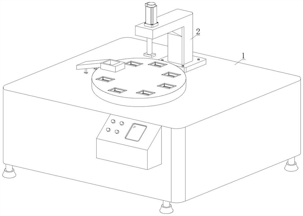
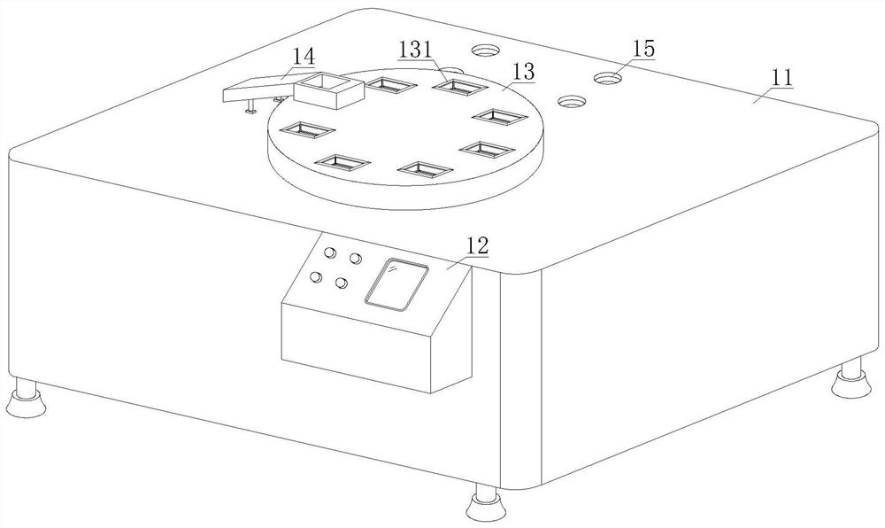
[0039] see Figure 1-2And 9, an anisotropic reluctance magnetic head assembly equipment, including a console 1 and a press-in device 2, the press-in device 2 is threaded on the upper end side of the console 1, and the console 1 includes a table 11, a manipulation device 12, Turntable 13, blanking device 14 and threaded hole 15, control device 12 is installed on the front side of table top 11, and rotating disk 13 is installed on the upper end of table top 11, and unloading device 14 is installed on the upper end side of table top 11, and unloading device One end of 14 is positioned at the vertical upper end turntable 13, and the upper end side of table top 11 is provided with threaded hole 15, and the inner chamber screw thread of threaded hole 15 is equipped with pressing device 2; Cylinder 23 and depression bar 24, the upper end of base plate 21 is equipped with right-angled frame 22, and the upper end side of right-angled frame 22 is equipped with first cylinder 23, and the...

Embodiment approach , 1 Embodiment approach

[0043] In order to further and better explain the above-mentioned embodiments, the present invention also provides an embodiment, a method for implementing an anisotropic magneto-resistive magnetic head assembly device, comprising the following steps:

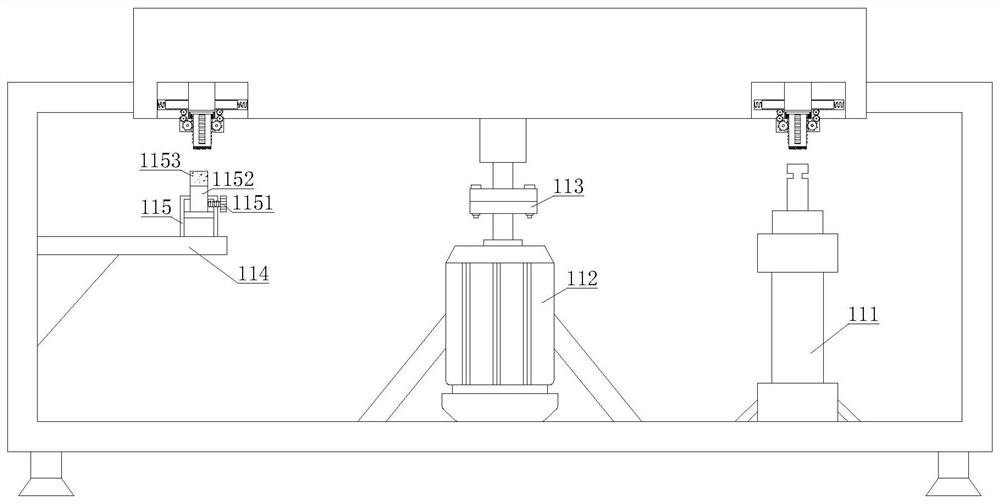
[0044] S01: After the material enters the inner cavity of the charging trough 131, the servo motor 112 rotates to drive the turntable 13 to rotate. When the turntable 13 is rotating, the chute 1323 at the lower end of the telescopic push rod 132 is slidingly connected with the second cylinder 111. Each rotation The angle is just at the lower end of the pressure rod 24;

[0045] S02: After the charging tank 131 rotates to the lower end of the pressure rod 24, the second cylinder 111 drives the telescopic push rod 132 to descend, and the telescopic push rod 132 descends to drive the first-stage gear 1331, the second-stage gear 1332 and the third-stage gear 1333 to rotate, The three-stage gear 1333 drives the first push rod 1312 t...

Embodiment 2

[0050] see Figure 1-2 And 9, an anisotropic reluctance magnetic head assembly equipment, including a console 1 and a press-in device 2, the press-in device 2 is threaded on the upper end side of the console 1, and the console 1 includes a table 11, a manipulation device 12, Turntable 13, blanking device 14 and threaded hole 15, control device 12 is installed on the front side of table top 11, and rotating disk 13 is installed on the upper end of table top 11, and unloading device 14 is installed on the upper end side of table top 11, and unloading device One end of 14 is positioned at the vertical upper end turntable 13, and the upper end side of table top 11 is provided with threaded hole 15, and the inner chamber screw thread of threaded hole 15 is equipped with pressing device 2; Cylinder 23 and depression bar 24, the upper end of base plate 21 is equipped with right-angled frame 22, and the upper end side of right-angled frame 22 is equipped with first cylinder 23, and th...


PUM


Abstract

The invention discloses anisotropic magnetoresistive head assembling equipment. The equipment comprises an operation table and a press-in device; the press-in device is installed at one side of the upper end of the operation table in a threaded mode; when a second air cylinder continuously descends for clamping, a push plate compresses a second spring to retract under the pushing force of clamping, and therefore material assembling is prevented from being damaged due to the fact that the clamping force of first push rods is too large; and after the second air cylinder ascends, a telescopic push rod ascends together, so that the first push rods are driven by a third-level gear to retract, the push plate automatically stretches out under the elastic force reset of the second spring, and therefore next-time positioning and clamping are facilitated. Meanwhile, the invention further discloses an implementation method of the anisotropic magnetoresistive head assembling equipment; a servo motor rotates to drive a rotary disc to rotate; when the rotary disc rotates; a sliding groove at the lower end of the telescopic push rod is in sliding connection with the second air cylinder; and aftera material loading groove rotates to the lower end of a pressing rod, the two pairs of first push rods extend out at the same time to fixedly clamp materials, so that the positioning and the fixing effects are achieved, and the pressing rod can press materials conveniently.

Description

technical field [0001] The invention relates to the technical field of anisotropic reluctance magnetic head assembly equipment, in particular to an anisotropic reluctance magnetic head assembly equipment and an implementation method thereof. Background technique [0002] A magnetic head refers to a component that reads data on a magnetic medium through magnetic principles. Common magnetic heads include hard disk heads, tape recorder heads, etc. The magnetic head of the hard disk is the key component of the hard disk to read data. Its main function is to convert the magnetic information stored on the hard disk into electrical signals and transmit it to the outside. Its working principle is to use the resistance value of special materials to change with the The principle of magnetic field change is used to read and write data on the disk. The quality of the magnetic head determines the storage density of the hard disk to a large extent. During the assembly of the magnetic he...

Claims


Application Information

Patent Timeline
Patent Type & Authority Applications(China)
IPC IPC(8): B23P19/027B65G47/82G11B5/105G11B5/39
CPCB23P19/027B65G47/82G11B5/105G11B5/39
Inventor 古国军黄才晶古东昌李媛梅
Owner 全南群英达电子有限公司
Learn More