A foaming device for foamed asphalt

A foaming equipment and technology of foamed asphalt, which is applied in the processing of tar asphalt/petroleum asphalt/natural asphalt, petroleum industry, etc., can solve problems such as low thermal conductivity, affect the foaming index of asphalt, and reduce the amount of foam, and achieve the degree of dispersion The effect of homogenization

Active Publication Date: 2021-07-23
山东道诺工程设备有限公司
View PDF5 Cites 0 Cited by
  • Summary
  • Abstract
  • Description
  • Claims
  • Application Information

AI Technical Summary

Problems solved by technology

[0002] As an excellent waterproof material and anti-corrosion material, foamed asphalt is widely used in industrial production industries. It needs to be heated during production. After heating, the surface tension generated by the asphalt film during the expansion process resists the steam pressure until it is balanced. Due to the low relationship between asphalt and water Thermal conductivity, the equilibrium state can generally be maintained for a few seconds, a large number of bubbles are generated during the foaming process and exist in a metastable state, but the foam is easy to burst because the foam has a nearly stable honeycomb structure of air cells , where multiple air bubbles gather, the liquid film is bent and concave toward the air chamber to form a Platt boundary, and the liquid will flow from the small curvature to the Platt junction. This drainage effect will gradually thin the liquid film, When the liquid film reaches a critical thickness, the film will burst, which means that the amount of foam will decrease, which will seriously affect the foaming index of asphalt. Based on the above premise, a foaming equipment for foaming asphalt was developed in this case to solve this problem.

Method used


Image

  • A foaming device for foamed asphalt
  • A foaming device for foamed asphalt
  • A foaming device for foamed asphalt

Examples


Embodiment

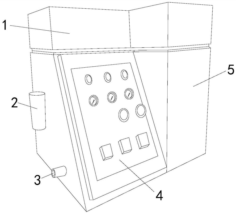
[0023] see figure 1 , the present invention provides a foaming equipment for foamed asphalt, the structure of which includes: a control box 1, an electric control box 2, an external connection pipe 3, an operation panel 4, and a foaming box 5, and the sides of the control box 1 are respectively equipped with electric The control box 2 and the external connection pipe 3 are connected to the operation panel 4 at the front position. The foam box 5 is located on the side of the control box 1 and the two are connected to each other. The control box 1 is the main structure of the equipment, mainly as the outer shell of the equipment to the inside Circuit components and mechanical components are protected, and the shell formed by trapezoidal geometry combined with a cuboid can divide the control area and the asphalt foaming area. The panel realizes the viewing of the command parameters and operation instructions of the equipment, and controls the operation of the equipment. The elec...

Embodiment 2

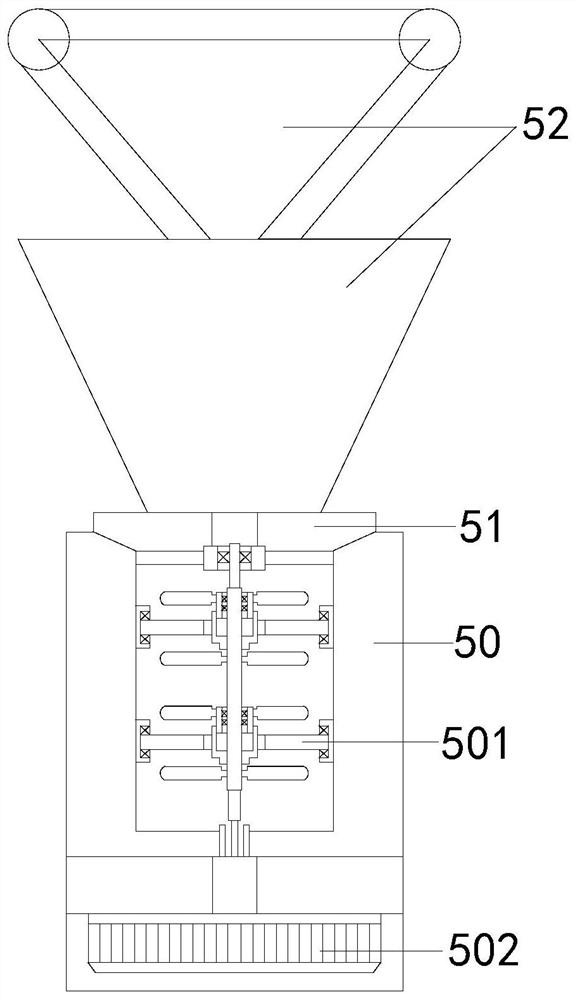
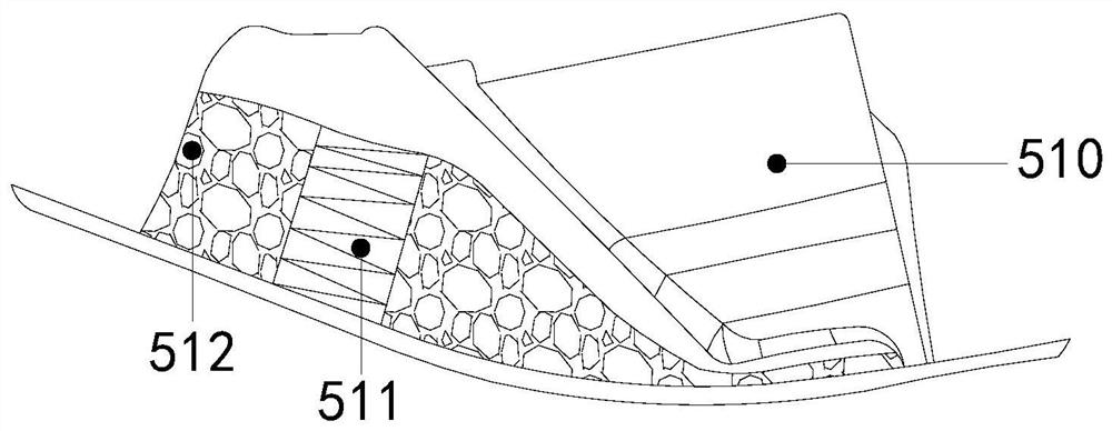
[0029] The description of the second embodiment drawn in conjunction with the first embodiment, combined with image 3 , Figure 4 and Figure 5 The upper and lower ends of the base point suspension 510 are connected to the anti-spring tube 511, and the side of the anti-spring tube 511 is provided with an air bag 512 connected thereto. Connected with it, the air intake triangular bucket 520 is located at the top of the structure of the bubble increasing bucket 52, and its bottom end runs through the uniform distribution box 540 connected to the swing frame 51 and the drive frame 50 at the same time. The ring plate 5300 is provided with a shaft 5301 and its There are honeycomb grooves 5302 and slide rails 5303 distributed on the side, the moving wheel 5304 fits and connects to the slide rail 5303 and its side is connected to the honeycomb wheel 5305, when in use, the asphalt raw material is put into the air intake triangular bucket 520, and one end of the gas injection pipe 52...


PUM


Abstract

The invention discloses a foaming equipment for foamed asphalt. The structure comprises: a control box, an electric control box, an external connection pipe, an operation panel, and a foaming box. Its front position is connected to the operation panel, and the foaming box is located on one side of the control box and the two are connected to each other. The beneficial effect of the present invention is that the structure of the swinging frame and the foaming bucket are used to contact each other in the asphalt liquid and increase the generation ratio of the liquid film. , transforming from a liquid film into abundant bubbles and relying on the structure to make its dispersion in the liquid uniform.

Description

technical field [0001] The invention relates to the industrial field, in particular to a foaming equipment for foamed asphalt. Background technique [0002] As an excellent waterproof material and anti-corrosion material, foamed asphalt is widely used in industrial production industries. It needs to be heated during production. After heating, the surface tension generated by the asphalt film during the expansion process resists the steam pressure until it is balanced. Due to the low relationship between asphalt and water Thermal conductivity, the equilibrium state can generally be maintained for a few seconds, a large number of bubbles are generated during the foaming process and exist in a metastable state, but the foam is easy to burst because the foam has a nearly stable honeycomb structure of air cells , where multiple air bubbles gather, the liquid film is bent and concave toward the air chamber to form a Platt boundary, and the liquid will flow from the small curvature...

Claims


Application Information

Patent Timeline
Patent Type & Authority Patents(China)
IPC IPC(8): C10C3/00
CPCC10C3/00
Inventor 张荣祥
Owner 山东道诺工程设备有限公司
Why Eureka
Try Eureka