
Assembly type prefabricated wallboard installation construction method

A technology of prefabricated wall panels and construction methods, which is applied to the preparation of building components on site, pillars, buildings, etc., and can solve problems such as large butt joint deviation of wall panels, toppling of walls, and affecting the stability of butt joints

Active Publication Date: 2020-12-15
重庆君道渝城绿色建筑科技有限公司
View PDF7 Cites 13 Cited by
  • Summary
  • Abstract
  • Description
  • Claims
  • Application Information

AI Technical Summary

Problems solved by technology

[0005] The present invention can solve the problem that the existing prefabricated wall panel installation device cannot stably lock the wall panel during the installation of the wall panel, resulting in instability of the prefabricated wall panel, and deviation of the wall panels during docking, which affects the stability of the docking and the stability after installation It can also solve the problem that the existing prefabricated wall panel installation device cannot stably support the prefabricated wall panel, which will cause the prefabricated wall panel to shake when it is installed and docked, and the position of the support rod cannot be adjusted according to the width of the wall panel, resulting in support The position is fixed, the support effect is poor, and the angle of the support rod cannot be adjusted according to the length of the prefabricated wall panel, resulting in unstable support points, and in severe cases, it will lead to excessive deviation of the wall panel docking and cause the wall to topple over, and the problem of poor safety performance

Method used


Image

  • Assembly type prefabricated wallboard installation construction method
  • Assembly type prefabricated wallboard installation construction method
  • Assembly type prefabricated wallboard installation construction method

Examples


Embodiment Construction

[0035] The embodiments of the present invention will be described in detail below with reference to the accompanying drawings, but the present invention can be implemented in many different ways defined and covered by the claims.

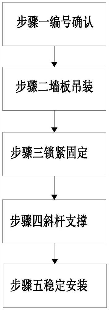
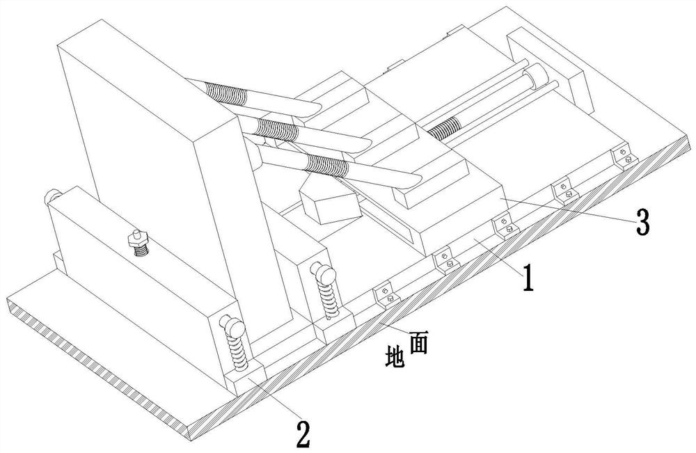
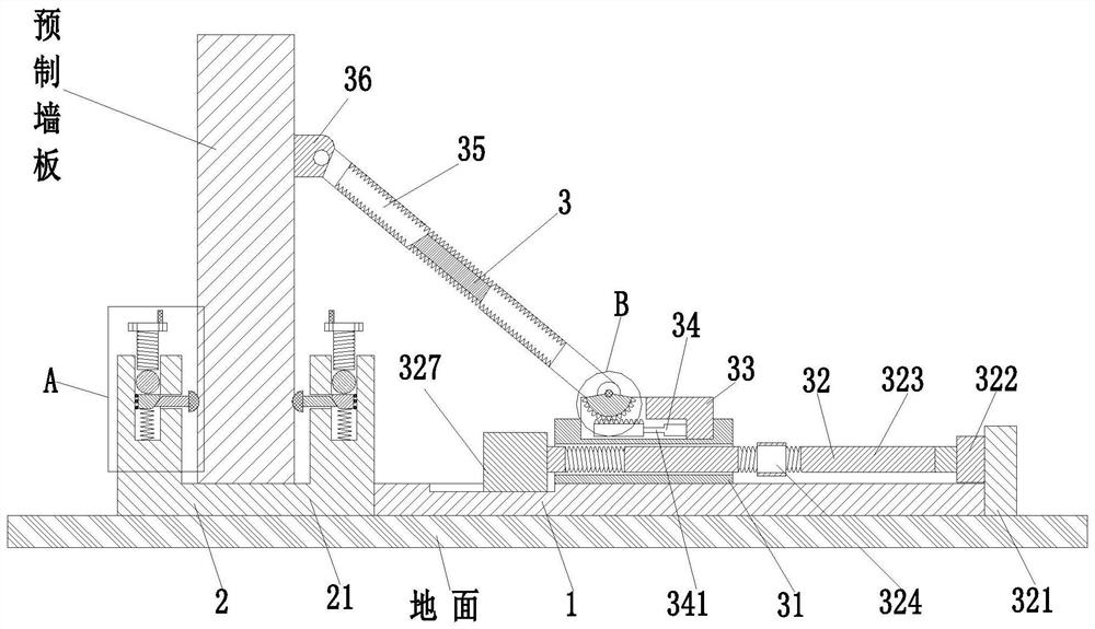
[0036] Such as Figure 1 to Figure 8 As shown, a prefabricated prefabricated wall panel installation construction method, which uses an auxiliary installation device, the auxiliary installation device includes a bottom plate 1, a locking mechanism 2 and a diagonal bracing mechanism 3, and a lock is installed on the left end surface of the bottom plate 1. Tightening mechanism 2, the right side of the upper end surface of base plate 1 is equipped with diagonal bracing mechanism 3.

[0037]The locking mechanism 2 includes a yoke frame 21, a locking bolt 22, a rotating compass 23, a rotating rod 24, a sliding pressure rod 25, a first locking branch chain 26, a limit ring 27, an ear seat 28 and a telescopic Spring 29, the left end surface of the bottom ...


PUM


Abstract

The invention relates to an assembly type prefabricated wallboard installation construction method. An auxiliary installation device is used and comprises a bottom plate, a locking mechanism and an inclined strut mechanism, wherein the locking mechanism is installed on the left end face of the bottom plate, and the inclined strut mechanism is installed on the right side of the upper end face of the bottom plate. The problems that an existing prefabricated wallboard installation device cannot stably lock a wallboard during wallboard installation, consequently, the prefabricated wallboard is unstable, deviation can happen during wallboard butt joint, the butt joint stability and the stability after installation are influenced, the prefabricated wallboard cannot be stably supported, consequently, the prefabricated wallboard can shake during installation butt joint, the position of a supporting rod cannot be adjusted according to the width of the wallboard, the supporting position is fixed, the supporting effect is poor, the angle of the supporting rod cannot be adjusted according to the length of the prefabricated wallboard, supporting points are unstable, and in severe cases, the wallboard butt joint deviation is too large, consequently, a wall topples over, and safety performance is poor can be solved.

Description

technical field [0001] The invention relates to the technical field of prefabricated buildings, in particular to a construction method for installing prefabricated wall panels. Background technique [0002] Prefabricated prefabricated wall panels refer to reinforced concrete panel components processed in prefabricated factories or construction sites for building assembly. The use of prefabricated concrete wall panels to build prefabricated large-slab buildings can improve the degree of factory and mechanized construction, reduce on-site wet work, save on-site labor, overcome seasonal influences, and shorten the construction period. Prefabricated buildings are different from traditional construction models. The architectural model of building components including wall panels, balconies, and stairs is pre-formed in the workshop and hoisted by tower cranes on the construction site. It has the advantages of high production efficiency, low cost, and short construction period, and...

Claims


Application Information

Patent Timeline
Patent Type & Authority Applications(China)
IPC IPC(8): E04G21/26E04G21/14E04G21/16E04G25/06E04G25/04
CPCE04G21/147E04G21/167E04G21/26E04G25/04E04G25/06
Inventor 冒鹏飞
Owner 重庆君道渝城绿色建筑科技有限公司
Learn More