Seal type disposable drawer lock

A one-time, drawer lock technology, applied in the field of medical equipment, can solve the problems of high cost and complex structure, and achieve the effect of convenient production, low cost and easy access

Pending Publication Date: 2020-12-15
杨骏成
View PDF1 Cites 0 Cited by
  • Summary
  • Abstract
  • Description
  • Claims
  • Application Information

AI Technical Summary

Problems solved by technology

However, the structure of this lock is complicated, the cost is high, and a large force is required to open the lock. Therefore, the applicant has invented a disposable drawer lock structure that is easy to use and lower in cost, and is easier to manage.

Method used


Image

  • Seal type disposable drawer lock
  • Seal type disposable drawer lock
  • Seal type disposable drawer lock

Examples


Embodiment 1

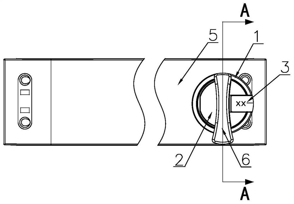
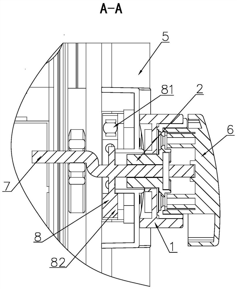
[0023] Embodiment 1: A kind of seal type disposable drawer lock, such as Figure 1 ~ Figure 2 As shown, it includes a lock base 1, a rotating lock cylinder 2, a disposable lock sticker 3, a drawer panel 5, a rotating handle 6, an eccentric lock head 7 and a limit suction assembly 8, and the lock base 1 is fixedly installed on the drawer panel 5 , the rotary lock cylinder 2 passes through the central through hole of the lock base 1 and is rotatably set on the lock base 1, the rotary handle 6 is fixedly installed on the outer surface of the rotary lock core 2, and the length of the hand-held section of the rotary handle 6 is longer than that of the rotary lock core 2 The length of the eccentric lock head 7 is fixedly installed on the inner surface of the rotary lock cylinder 2, the eccentric lock head 7 is arranged on the inner surface of the drawer panel 5, the limit suction assembly 8 includes a limit piece 81 and a suction piece 82, the limit The piece 81 and the suction piec...

Embodiment 2

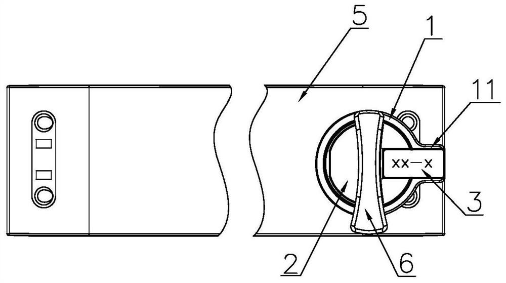
[0024] Embodiment 2: The difference with Embodiment 1 is that, as image 3 As shown, a locking protrusion 11 is provided on the outer side of the lock base 1, the upper surface of the locking protrusion 11 is flush with the upper surface of the lock base 1, and the upper surface area of ​​the locking protrusion 11 is greater than or equal to the one-time locking 3 fit area.

Embodiment 3

[0025] Embodiment 3: The difference with Embodiment 1 is that, as Figure 4 As shown, a limiting structure 4 is arranged between the lock seat 1 and the rotating lock cylinder 2, the limiting structure 4 is a limiting convex body 41 and a limiting block 42, and the two limiting convex bodies 41 are fixed symmetrically on the lock On the outer upper surface of the seat 1, the connection line of the two limiting protrusions 41 is perpendicular to the disposable lock sticker 3, the limiting block 42 is fixedly arranged on the outer surface of the rotating lock cylinder 2, and the limiting protrusions 41 protrude from the lock. The height of the outer surface of the seat 1 is higher than the height of the bottom surface of the limit block 42 , and the rotation angle of the rotary lock cylinder 2 is limited by the limit structure 4 .


PUM


Abstract

The invention provides a seal type disposable drawer lock. The seal type disposable drawer lock comprises a lock base, a rotary lock cylinder and a disposable lock sticker, wherein the rotary lock cylinder penetrates through a center through hole of the lock base and is rotationally arranged on the lock base in a sleeving mode; the disposable lock sticker is transversely and fixedly attached to the outer surface of the rotary lock cylinder and the outer surface of the lock base; and the rotary lock cylinder is fixed to the lock base, a drawer is locked, and a serial number is arranged on the disposable lock sticker. According to the structure of the drawer lock, the medicine storage and use safety is guaranteed, the medicine management efficiency is high, the error rate is low, the structure is simple, and use is convenient and fast and saves labor. The risk that medical staff lose keys is eradicated, a record is made every time the drawer is opened, and later source tracing is facilitated if the medical staff forget to register the record.

Description

technical field [0001] The invention relates to the technical field of medical devices, in particular to a disposable drawer lock structure for medicine access. Background technique [0002] Drug management has always been a difficult problem for every hospital. At present, in China, special drugs including anesthetics and non-anesthetics in operating rooms are stored in the drawers of ordinary drug cabinets and medical trolleys. In order to better manage drugs, they must be registered, especially controlled drugs. It is manually registered by drug administrators or medical staff. Medicine cabinets and medical trolley drawers must be strictly controlled for lock control, but the existing locks are all of ordinary lock structure, and this lock structure needs to be opened and closed with a key. If this kind of lock structure is not registered in time by the medical staff when taking it, the source cannot be checked later, it is difficult to ensure the safety of drug storage...

Claims


Application Information

Patent Timeline
Patent Type & Authority Applications(China)
IPC IPC(8): E05B39/04E05B65/46
CPCE05B39/04E05B65/46
Inventor 杨骏成
Owner 杨骏成
Why Eureka
Try Eureka