Axial flow ventilator or fan with automatic oscillating mechanism

An axial flow fan and automatic technology, applied in the direction of machines/engines, liquid fuel engines, mechanical equipment, etc., can solve the problems of insufficient air volume, large vibration, short range, etc., and achieve the effect of improving static pressure efficiency and preventing loosening

Pending Publication Date: 2020-12-15
佛山市赛达通风机有限公司
View PDF0 Cites 1 Cited by
  • Summary
  • Abstract
  • Description
  • Claims
  • Application Information

AI Technical Summary

Problems solved by technology

[0005] Aiming at the deficiencies of the prior art, the present invention provides an axial flow fan or fan with an automatic shaking head mechanism, which has the advantages of low noise, small vibration, large air volume, long range, easy maintenance and automatic head shaking, etc., and solves the problem of traditional axial flow. When the flow fan is used as a free fan, it will appear that the noise is large, the vibration is large and the range is short, and when the installation position is limited, it is not easy to maintain and show the situation of insufficient air volume. At the same time, the existing axial flow fan is not easy to adjust its Use orientation so that it has certain limitations

Method used


Image

  • Axial flow ventilator or fan with automatic oscillating mechanism
  • Axial flow ventilator or fan with automatic oscillating mechanism
  • Axial flow ventilator or fan with automatic oscillating mechanism

Examples


Embodiment Construction

[0024] The following will clearly and completely describe the technical solutions in the embodiments of the present invention with reference to the accompanying drawings in the embodiments of the present invention. Obviously, the described embodiments are only some, not all, embodiments of the present invention. Based on the embodiments of the present invention, all other embodiments obtained by persons of ordinary skill in the art without making creative efforts belong to the protection scope of the present invention.

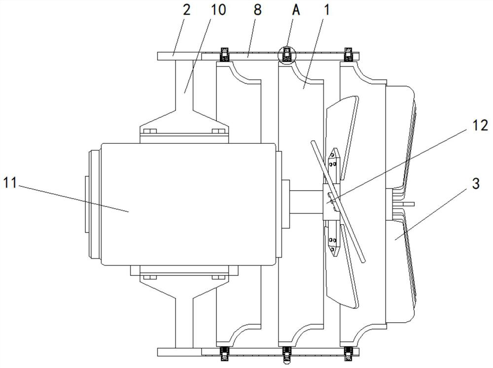
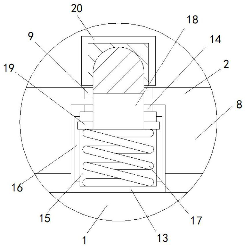
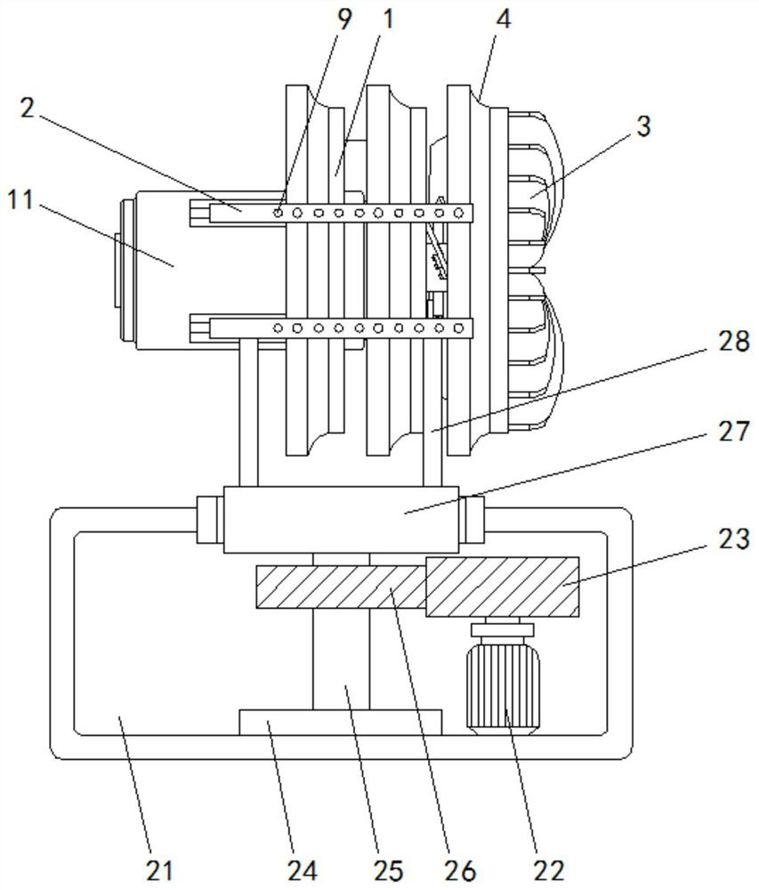
[0025] see Figure 1-4 , an axial flow fan or fan with an automatic shaking head mechanism, comprising a base 21, three segmented air cylinder units 1 in number and four connectors 2 in number, and the segmented air cylinder unit 1 is a circle Arc-shaped, conical or other shapes, and the side of the segmented air cylinder unit 1 is an arc edge 4, and the four connecting pieces 2 are symmetrically distributed on the outside of the segmented air cylinder unit 1....


PUM


Abstract

The invention relates to the technical field of axial flow ventilators (fans) and discloses an axial flow ventilator or fan with an automatic oscillating mechanism. The axial flow ventilator or fan comprises a base, three sectional type wind cylinder units and four connecting parts. The four connecting parts are symmetrically distributed on the exteriors of the sectional type wind cylinder units in pairs. Guide blades are fixedly connected to the right side of the sectional type wind cylinder unit on the right side. According to the axial flow ventilator or fan with the automatic oscillating mechanism, a sectional type wind cylinder is formed by assembling the sectional type wind cylinder units and the connecting parts, so that airflow does not rotate by a long distance in the wind cylinder, and generation of violent airflow noise and vibration is avoided. Meanwhile, when an installing position is limited, input wind can be supplemented through gaps among the disconnected type wind cylinder units. A sliding groove is formed in each connecting part, the sectional type wind cylinder units are provided with sliding blocks matched with the sliding grooves, and thus the sectional type wind cylinder units slide between the four connecting parts conveniently through the sliding blocks and the sliding grooves.

Description

technical field [0001] The invention relates to the technical field of axial flow fans (fans), in particular to an axial flow fan or fan with an automatic head shaking mechanism. Background technique [0002] Axial flow fans are widely used for ventilation in factories, mines, tunnels, cooling towers, vehicles and ships, and can also be used for ventilation or enhanced heat dissipation in metallurgy, chemical industry, light industry, food, medical equipment, mechanical equipment and civil buildings. It can also be used as a free fan. [0003] Existing axial flow fans generally set the impeller in a cylindrical air duct. Since the air flow rotates strongly in the air duct, when it is used as a free fan, it will generate a lot of airflow noise and vibration. At the same time, the blown out Due to the absence of duct constraints, the airflow quickly scatters, showing the phenomenon that there is wind at a short distance, and the wind speed drops sharply at a little distance, ...

Claims


Application Information

Patent Timeline
IPC IPC(8): F04D25/10F04D29/64F04D29/66
CPCF04D25/105F04D29/646F04D29/667
Inventor 麦鸿杰孙峰
Owner 佛山市赛达通风机有限公司
Why Eureka
Try Eureka