A sensor rapid detection device

A detection device and sensor technology, which is applied in the field of sensor detection, can solve problems such as troublesome fixing and taking out of sensors, ground shattering, and affecting detection efficiency, so as to save trouble in fixing and taking out sensors, prevent shattering of the ground, and improve detection efficiency Effect

Active Publication Date: 2021-05-25
厦门安科科技有限公司
View PDF10 Cites 0 Cited by
  • Summary
  • Abstract
  • Description
  • Claims
  • Application Information

AI Technical Summary

Problems solved by technology

[0004] Before the sensor is used, the performance of the sensor needs to be tested to ensure that the sensor used is a qualified product. The sensor detection device in the prior art is troublesome when fixing and taking out the sensor, and it is difficult to intuitively and quickly determine whether the sensor is qualified. product, which seriously affects the detection efficiency. In addition, the sensor detection device in the prior art is inconvenient to move and use. It vibrates greatly during work, and there is a hidden danger of cracking the ground.

Method used


Image

  • A sensor rapid detection device
  • A sensor rapid detection device
  • A sensor rapid detection device

Examples


Embodiment 1

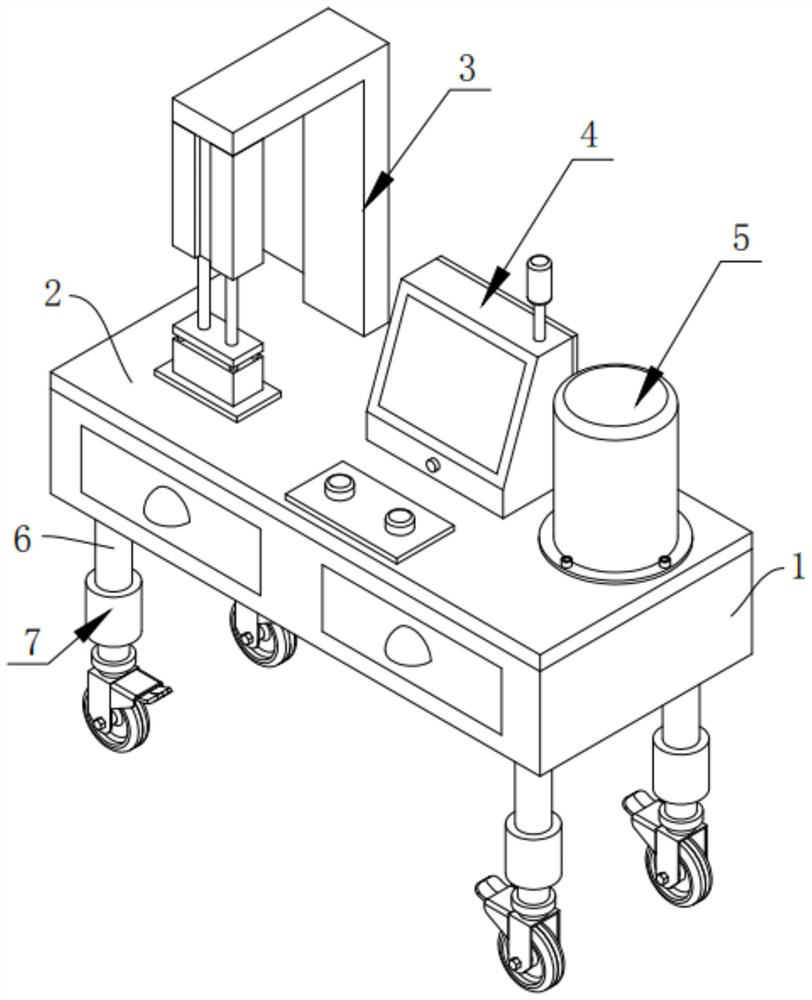
[0054] like Figure 1-Figure 3 As shown, a sensor rapid detection device according to an embodiment of the present invention includes a base 1, a station fixing mechanism 3, a parameter display mechanism 4 and an operation panel 8;

[0055] Among them, such as figure 1 As shown, the upper part of the base 1 is fixedly installed with a support plate 2, and the bottom of the base 1 is fixedly installed with four symmetrically arranged legs 6;

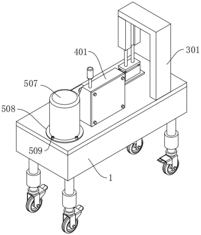
[0056] Among them, such as figure 1 , Figure 5-Figure 8 As shown, the station fixing mechanism 3 includes an L-shaped fixing frame 301, a telescopic cylinder 302, a fixing plate 303, a guide sleeve 306, two metal rods 310, a through groove 304, a supporting piece 307, a connecting plate 305, and a rubber pressing block 311 and four rubber blocks 312, the L-shaped fixed frame 301 is fixedly installed on the upper part of the support plate 2, and the telescopic cylinder 302 is vertically and fixedly installed at the bottom of the inner ...

Embodiment 2

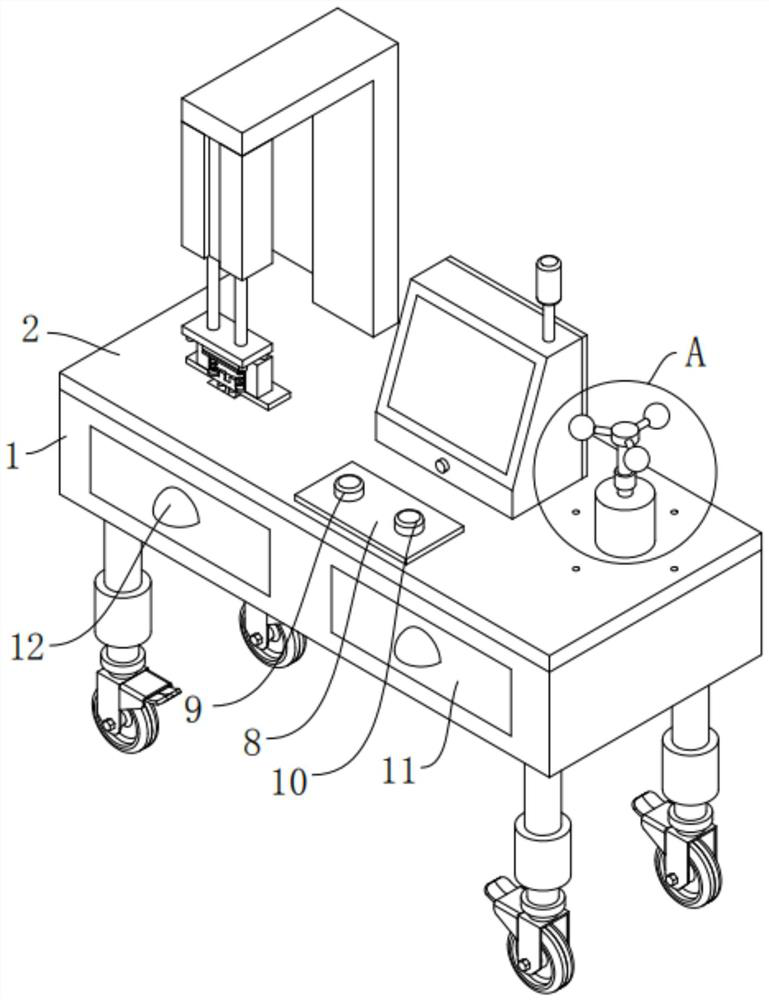
[0062] like Figure 1-Figure 4 As shown, the difference between this embodiment and Embodiment 1 is that it also includes an actuator 5, and the actuator 5 includes a motor 501, a rotating shaft 502, an assembly block 503, three connecting rods 504, and three spherical blocks 505 and a cylindrical protective shell 507, the motor 501 is vertically and fixedly installed on the upper part of the support plate 2, the rotating shaft 502 is vertically arranged, and the bottom end of the rotating shaft 502 passes through a coupling 506 It is fixedly connected with the rotating shaft of the motor 501, the fitting block 503 is fixedly mounted on the upper end of the rotating shaft 502, and the three connecting rods 504 are fixedly mounted on the side of the fitting block 503 , and the three connecting rods 504 are arranged in a circumferential equiangular manner around the fitting block 503, and the three spherical blocks 505 are respectively fixedly installed on the ends of the three ...

Embodiment 3

[0065] like image 3 As shown, the difference between this embodiment and Embodiment 2 is that the inside of the base 1 is a hollow structure, and the front part of the base 1 is provided with two symmetrically arranged drawers 11, and the two drawers 11 Buckle hands 12 are all fixedly installed on the outer end faces.

[0066] By adopting the above technical solution, the drawer 11 can be used to store the unqualified sensors, which is convenient for the process personnel to analyze the problems of the unqualified sensors later, and facilitates the improvement of the process and the increase of the yield rate.


PUM


Abstract

The invention discloses a sensor rapid detection device, which comprises a base, a station fixing mechanism, a parameter display mechanism and an operation panel. A support plate is fixedly installed on the upper part of the base, and four symmetrically arranged legs are fixedly installed on the bottom of the base. The station fixing mechanism includes an L-shaped fixing frame, a telescopic cylinder, a fixing plate, a guide sleeve, two metal rods, a through groove, a support piece, a connecting plate, a rubber pressing block and four rubber blocks. The parameter display mechanism includes a box body, a rear Cover, controller, signal indicator light, touch display screen and power switch, the operation panel is fixedly installed on the upper part of the support plate, and the operation panel is symmetrically provided with pressing buttons and release buttons. The present invention saves trouble when fixing and taking out the sensor, can intuitively and quickly determine whether the sensor is a qualified product, can greatly improve the detection efficiency, is easy to move, easy to use, easy to lock the position, and has less vibration during work, which can prevent vibration Crack the ground.

Description

technical field [0001] The invention relates to the technical field of sensor detection, in particular to a fast sensor detection device. Background technique [0002] Building construction refers to the production activities in the implementation stage of engineering construction. It is the construction process of various buildings. It can also be said to be the process of turning various lines on the design drawings into real objects at designated locations. It includes basic engineering construction, main structure construction, roofing engineering construction, decoration engineering construction, etc. [0003] In the process of building construction, various sensors are commonly used. These sensors collect data from the construction site, such as component temperature, deformation, force, equipment operation, and site construction conditions, that reflect useful information on various construction production factors and their states during construction. Image technolog...

Claims


Application Information

Patent Timeline
Patent Type & Authority Patents(China)
IPC IPC(8): G01D18/00
CPCG01D18/00
Inventor 钟松杏张阳川林宇鹏
Owner 厦门安科科技有限公司
Why Eureka
Try Eureka