
Vehicle-mounted antenna system for automatically tracking unmanned aerial vehicle

A vehicle-mounted antenna and automatic tracking technology, applied in the field of drones, can solve the problems of not being too large, increasing the difficulty of drones, and having fixed requirements for the relative speed of drones and ground antennas, etc., to achieve reduced frequency and large range , the effect of enhancing the strength

Pending Publication Date: 2020-12-15
深圳市贝贝特科技实业有限公司
View PDF14 Cites 0 Cited by
  • Summary
  • Abstract
  • Description
  • Claims
  • Application Information

AI Technical Summary

Problems solved by technology

[0003] At present, people have invented some different forms of UAV automatic tracking antenna system to enhance the strength of the signal received by UAV during flight; for example, the patent No. 201710954259.3 discloses a UAV automatic The tracking antenna system and its tracking method; can make the UAV antenna and the ground antenna realize real-time alignment under the control of the corresponding controller; The real-time relative position between the UAV and the ground antenna; to achieve this, there are fixed requirements for the positioning method and the relative speed between the UAV and the ground antenna should not be too large; this makes the automatic tracking method disclosed in this patent unsuitable Cases where ground antennas move
[0004] Nowadays, unmanned aerial vehicles that take off and land on static ground can no longer meet the needs of the majority of users, especially during natural disasters or outdoor work, it is difficult to set the landing position of the unmanned aerial vehicle at a certain point, but set it on the car; The man-machine needs to land on the vehicle, because the vehicle is still moving when the drone lands, which greatly increases the difficulty of landing the drone on the vehicle; therefore, there is an urgent need for a dynamic retractable Unmanned Automatic Tracking Antenna System

Method used


Image

  • Vehicle-mounted antenna system for automatically tracking unmanned aerial vehicle

Examples


Embodiment Construction

[0023] In order to express the present invention more clearly, the present invention will be further described below in conjunction with the accompanying drawings.

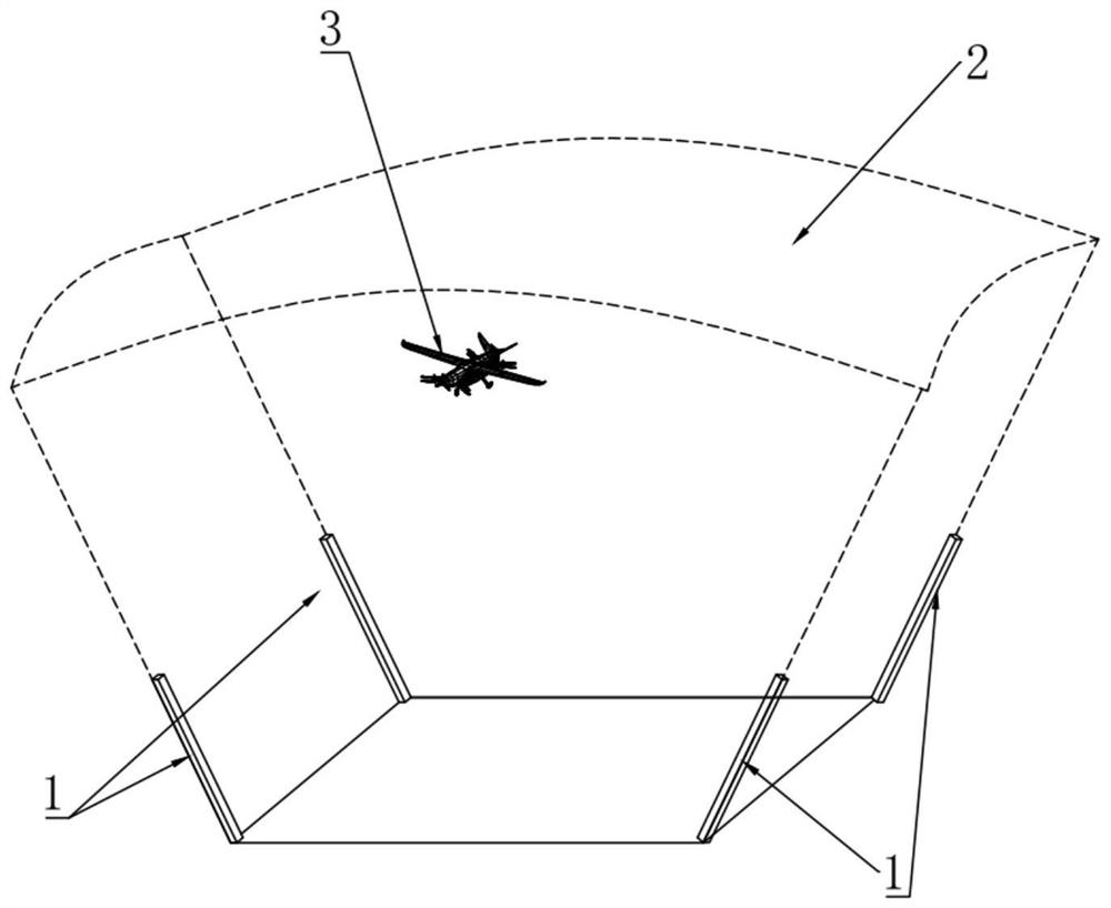
[0024] As mentioned in the background technology, as the application range of the UAV 3 becomes wider and wider, the traditional UAV 3 takes off or lands on a static ground and cannot meet the needs of the UAV 3 for outdoor work, especially When wars or natural disasters occur; more forms are to use vehicles to directly carry UAV 3 to outdoors for real-time collection of various data; but in the process of UAV 3 detecting various data outdoors, vehicles also need to rush On the way to the next point; traditionally, if the traditional antenna 1 is used to track the UAV 3 to obtain the data collected by the UAV 3 in real time, because the vehicle itself is also moving, the relative speed between the vehicle and the UAV 3 is large, and there is no The human-machine can fly out of the signal coverage of the ground ant...


PUM


Abstract

The invention discloses a vehicle-mounted antenna system for automatically tracking an unmanned aerial vehicle, which belongs to the field of unmanned aerial vehicles. The system comprises an ad-hoc network device with wide-angle signals, wherein the ad-hoc network device is formed by a plurality of antennas arranged at the top of a vehicle; a positioning device is used for acquiring the positionof the unmanned aerial vehicle in the wide-angle signal; a control device is used for adjusting the orientation of the wide-angle signal of the ad hoc network device according to the relative positionof the unmanned aerial vehicle and the ad hoc network device; compared with a traditional unmanned aerial vehicle with a single antenna arranged on the ground for tracking, the wide-angle signal range formed by the multiple antennas is large, even if the relative speed between the unmanned aerial vehicle and the vehicle is large, the unmanned aerial vehicle can still be located in the wide-anglerange for a long time, and only the angles of the antennas need to be finely adjusted to change the orientation of wide-angle signals or expand the range of the wide-angle signals; the unmanned aerialvehicle is made to be always in a wide-angle signal range; compared with the prior art, the frequency of adjusting the antenna angle is reduced, the requirement for the positioning precision of the unmanned aerial vehicle is lowered, and the strength of communication signals between the ground and the unmanned aerial vehicle is enhanced.

Description

technical field [0001] The invention relates to the field of drones, in particular to a vehicle-mounted antenna system for automatically tracking drones. Background technique [0002] UAVs have been favored by various countries in recent years. They can not only be used in military fields such as battlefield surveillance and early warning, but also have broad application prospects in civilian fields. It can carry a high-definition visible light or infrared camera system, and can easily enter areas that humans cannot reach for aerial reconnaissance and aerial photography, and can be used for terrain mapping, disaster monitoring, etc. [0003] At present, people have invented some different forms of UAV automatic tracking antenna system to enhance the strength of the signal received by UAV during flight; for example, the patent No. 201710954259.3 discloses a UAV automatic The tracking antenna system and its tracking method; can make the UAV antenna and the ground antenna real...

Claims


Application Information

Patent Timeline
Patent Type & Authority Applications(China)
IPC IPC(8): H01Q1/12H01Q1/32H01Q3/02
CPCH01Q1/125H01Q1/1264H01Q1/3208H01Q3/02
Inventor 孙亚飞张田
Owner 深圳市贝贝特科技实业有限公司
Learn More