
Adjustable passive compliance device for automated assembly of components

A passive compliance and automatic assembly technology, applied in metal processing, metal processing equipment, manufacturing tools, etc., can solve the problems of high rigidity, inability to accurately adjust the compliance center in real time, small rigidity performance, etc., and achieve small rigidity, compact structure, and light weight The effect of small positioning accuracy requirements

Active Publication Date: 2018-06-08
SHANGHAI JIAO TONG UNIV
View PDF4 Cites 0 Cited by
  • Summary
  • Abstract
  • Description
  • Claims
  • Application Information

AI Technical Summary

Problems solved by technology

[0003] Aiming at the defects that the existing device cannot accurately adjust the compliance center in real time, has high rigidity, and is not suitable for ensuring the passive safety of precision assembly, the present invention proposes an adjustable passive compliance device for automatic assembly of parts, which realizes passive compliance through the cam ejector mechanism. The compliance center adjustment of the compliance device, through the use of rotating joints and universal hinges at both ends of the elastic suspender to achieve small stiffness performance, and the simple control of passive compliance performance through the design of the cam shape line, so as to realize the adjustment of the compliance center along the z-axis of the central axis of the device Wide range of adjustment, better compliance performance, convenient and accurate control

Method used


Image

  • Adjustable passive compliance device for automated assembly of components
  • Adjustable passive compliance device for automated assembly of components
  • Adjustable passive compliance device for automated assembly of components

Examples


Embodiment Construction

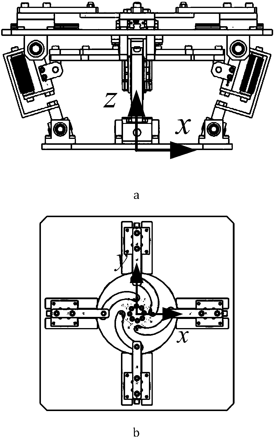
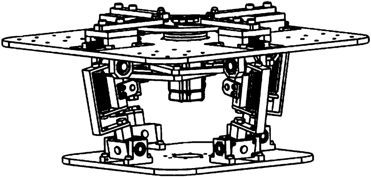
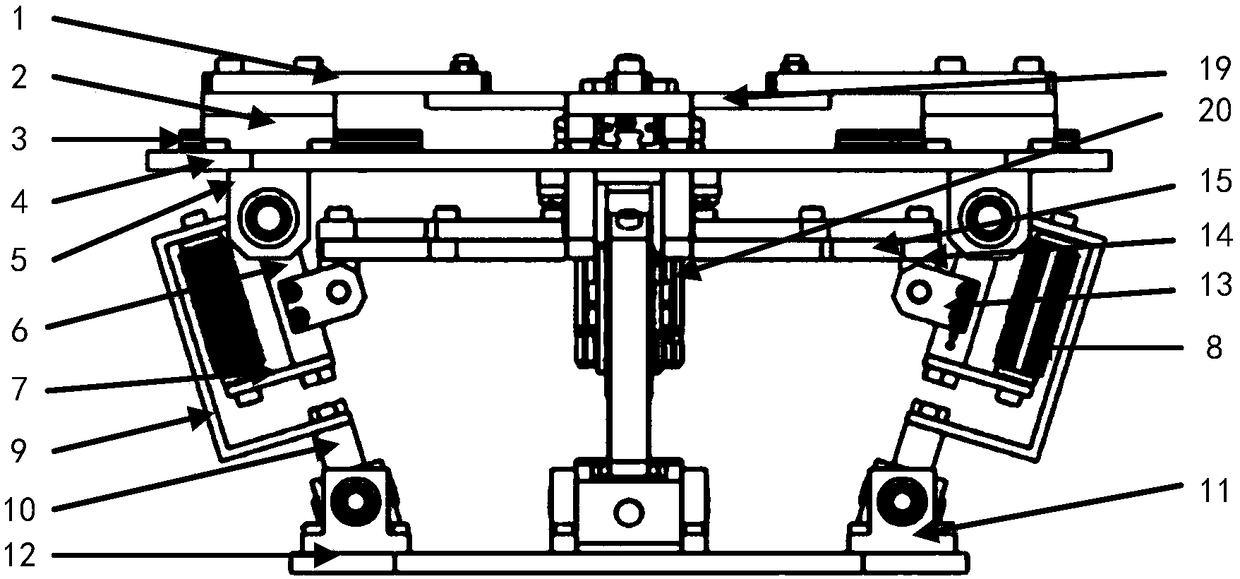
[0023] Such as figure 1 , 2 As shown, this embodiment includes: cam top rod 1, slider 2, slide rail 3, fixed platform 4, rotating sub-seat 5, upper swing rod 6, stopper 7, elastic unit 8, connecting piece 9, and lower swing rod 10. , U sub-seat 11, moving platform 12, rotating sub-seat 13, rotating joint 14, plane expansion mechanism 15, L-shaped connecting rod 16, rotating joint 17, harmonic reducer 18, cam 19, motor 20, rotating joint 21, Rotation joint 22.

[0024] The cam ejector mechanism includes: cam ejector 1, slider 2, slide rail 3, cam 19, harmonic reducer 18, and motor 20.

[0025] The elastic boom includes: a rotating sub-base 5, an upper swing rod 6, a baffle 7, an elastic unit 8, a connecting piece 9, and a lower swing rod 10. The upper end of the elastic boom is connected to the slider 2 through the rotating sub-base 5 , The lower end is connected with the movable platform 12 through the U sub-base 11.

[0026] The plane unfolding mechanism 11 includes eight L-shaped...


PUM


Abstract

The invention provides an adjustable passive adapting device used for component automatic assembly. The adjustable passive adapting device comprises a cam ejector rod mechanism, a plane unfolding mechanism, an elastic boom and a moving platform, wherein the cam ejector rod mechanism and the plane unfolding mechanism are separately arranged at the top and the bottom of a fixed platform, one end of the elastic boom is separately in rotating connection with the fixed platform and the plane unfolding platform, the other end of the elastic boom is in rotating connection with the moving platform, the cam ejector rod mechanism driven by a harmonic reducer drives the elastic boom to rotate, and the dip angle variation of the elastic boom is realized. The adjustment of the adapting center of the passive adapting device is realized through the cam ejector rod mechanism, small rigidity performance is realized by using a rotating pair and a universal hinge at the two ends of the elastic boom, and the simple control of passive adapting performance is realized by designing a cam outline, so that the adjustment of the adapting center along the central axis of the device, namely a z axle, is realized in a larger range, the adapting performance is better, and control is convenient and accurate. The adjustable passive adapting device is compact in structure, simple and accurate in control, great in support performance, small in rigidity and larger in the adjustable range of the adapting center.

Description

Technical field [0001] The invention relates to a device in the field of assembly technology, in particular to a passive compliance device with adjustable rigidity for precise assembly of a shaft between components. Background technique [0002] The assembly of low-pressure turbine shafts of turbofan engines and the assembly of large-scale components require the rigid assembly equipment to have extremely high positioning accuracy to avoid rigid contact and scratch the components. When the positioning accuracy cannot meet the requirements, a far-center passive compliance device can be used to ensure the passive safety of the component. The center of compliance has stiffness decoupling performance, compensating for assembly interference without causing other interference. However, the existing passive compliance devices have shortcomings such as small compliance performance adjustment range, high compliance center stiffness, and low adjustment accuracy. Aiming at this problem, an...

Claims


Application Information

Patent Timeline
Patent Type & Authority Patents(China)
IPC IPC(8): B23P19/00
CPCB23P19/00Y02P70/10
Inventor 王皓王卓识孔令雨陈根良赵勇余海东
Owner SHANGHAI JIAO TONG UNIV
Learn More