Clamping and force-measuring device for slow-wave components

A force measuring device and component technology, applied in the direction of electrical components, electrical components, etc., can solve the problems of complex structure, difficult to realize precise control of clamping motion loading force, etc., and achieve the effect of high assembly efficiency, simple structure, and precise assembly

Active Publication Date: 2017-10-13
GUANGZHOU INST OF ADVANCED TECH CHINESE ACAD OF SCI
View PDF4 Cites 0 Cited by
  • Summary
  • Abstract
  • Description
  • Claims
  • Application Information

AI Technical Summary

Problems solved by technology

In this scheme, the three-jaw chuck is used as the transmission device, and the structure is relatively complicated, and it is difficult to achieve precise control of the clamping movement and loading force during the assembly process

Method used


Image

  • Clamping and force-measuring device for slow-wave components
  • Clamping and force-measuring device for slow-wave components
  • Clamping and force-measuring device for slow-wave components

Examples


Embodiment Construction

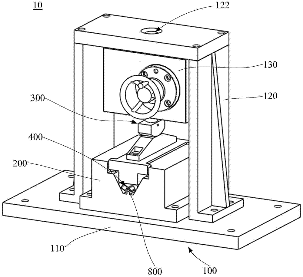
[0024] In order to facilitate the understanding of the present invention, the present invention will be described more fully below with reference to the associated drawings. Preferred embodiments of the invention are shown in the accompanying drawings. However, the present invention can be embodied in many different forms and is not limited to the embodiments described herein. On the contrary, these embodiments are provided to make the understanding of the disclosure of the present invention more thorough and comprehensive.

[0025] It should be noted that when an element is referred to as being “fixed” to another element, it can be directly on the other element or there can also be an intervening element. When an element is referred to as being "connected to" another element, it can be directly connected to the other element or intervening elements may also be present.

[0026] Unless otherwise defined, all technical and scientific terms used herein have the same meaning as...


PUM


Abstract

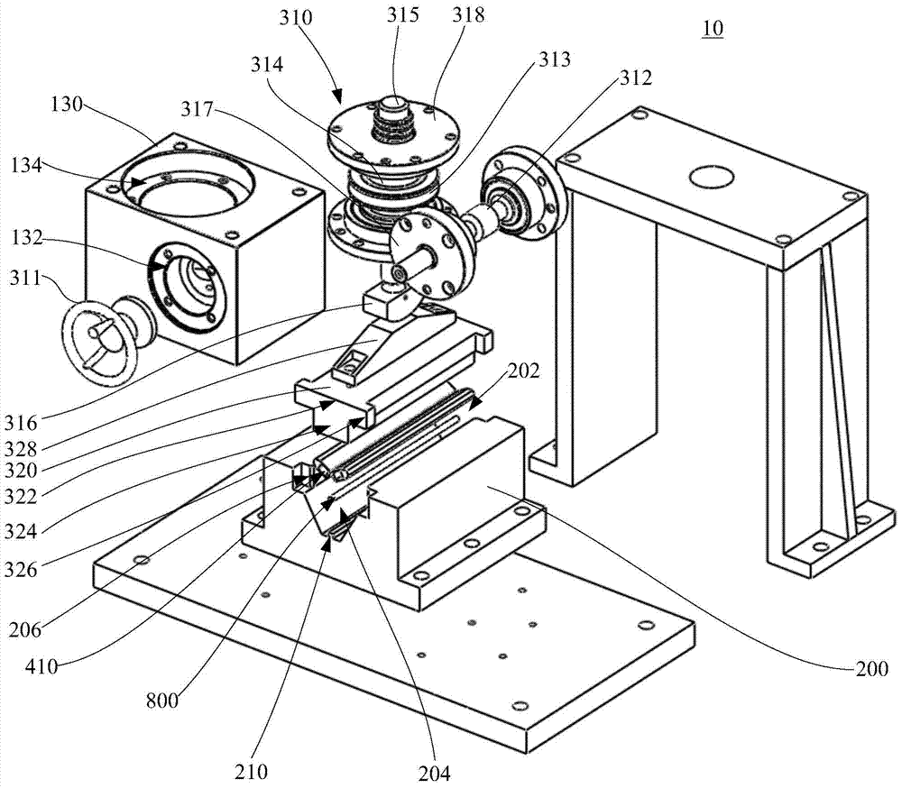
The invention relates to a clamping and force-measuring device for a slow-wave component tube shell, which comprises a support module, a lower pressing die, a displacement loading module and a force-measuring module. The clamping and force-measuring device of the slow-wave component shell can precisely measure and adjust the clamping movement and loading force. It adopts a symmetrical structure to evenly clamp the slow-wave component shell in the circumferential direction, which can reduce the influence of environmental factors on the measurement results. Therefore, the precise assembly of the slow wave component of the traveling wave tube can be realized, and the structure is simple and the assembly efficiency is high.

Description

technical field [0001] The invention relates to the field of assembly of microwave electronic devices, in particular to a clamping and force-measuring device for a slow-wave component shell. Background technique [0002] The assembly of the helical TWT slow-wave component is to assemble the helix and the clamping rod into the shell to achieve good contact between the shell, the clamping rod and the helix. In the actual assembly process, two assembly methods, cold spring pressing and hot extrusion, are often used. Among them, the cold elastic compression assembly method adopts the method of mechanically clamping the shell to generate elastic deformation to realize the clamping and fixing of the clamping rod and the helix. During the operation, the three clamping rods are required to be evenly distributed in the circumferential direction of 120°, and the deformation must be controlled within a certain range. The smooth introduction of the clamping rods and the helix can be re...

Claims


Application Information

Patent Timeline
Patent Type & Authority Patents(China)
IPC IPC(8): H05K13/04H05K13/08
Inventor 袁海梁济民张弓王卫军陈贤帅
Owner GUANGZHOU INST OF ADVANCED TECH CHINESE ACAD OF SCI
Why Eureka
Try Eureka