Photo machine pad type platform support structure and manufacturing method thereof

A technology of support structure and photo machine, applied in printing, printing device and other directions, can solve the problems of poor stability of the support structure of the photo machine platform, difficulty in ensuring the machining accuracy of the milling plane, lack of benchmarks for the assembly of the photo machine platform, etc., so as to reduce the processing time of the milling machine. , weight reduction, weight reduction effect

Active Publication Date: 2017-02-15
NEW CENTURY DIGITAL PRINT TECH
View PDF10 Cites 0 Cited by
  • Summary
  • Abstract
  • Description
  • Claims
  • Application Information

AI Technical Summary

Problems solved by technology

The existing photo machine platform is mainly installed on the installation plane of the base through the supporting pads connected to the bottom, the platform frame plate and the outriggers. At present, the installation plane of the base is a milling plane processed by a milling machine. Due to the limitation of the base length factor, it is difficult to ensure the machining accuracy of the milling plane when using conventional milling machine processing equipment to process the base installation plane, resulting in the lack of reference for the assembly of the photo machine platform. The existing technology uses the reference leg and the fine-tuning leg to cooperate. The reference leg installed at one end shall prevail. The straightness of the photo machine platform is ensured by adjusting each fine-tuning leg during assembly. The whole adjustment process is time-consuming and laborious, which greatly affects the assembly efficiency of the photo machine, and the photo machine platform supports The stability of the structure is poor, and it is easy to shift due to the vibration during transportation, which makes it difficult to transport the product

Method used


Image

  • Photo machine pad type platform support structure and manufacturing method thereof
  • Photo machine pad type platform support structure and manufacturing method thereof
  • Photo machine pad type platform support structure and manufacturing method thereof

Examples


Embodiment Construction

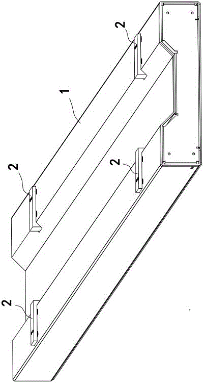
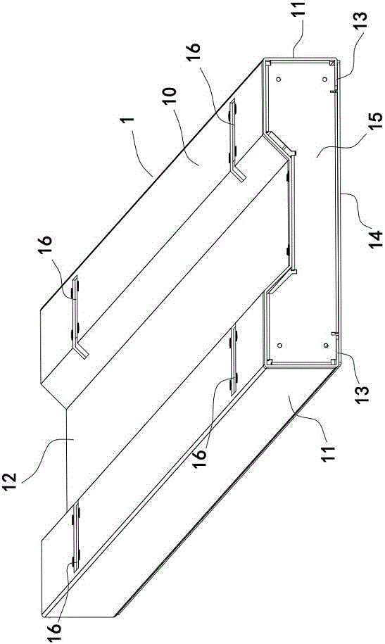
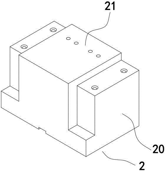
[0016] The pad type platform support structure of the photo machine of the present invention includes a base extending longitudinally, the base is as figure 1 , figure 2 , image 3 , Figure 4 As shown, it is mainly composed of a hollow shell 1 surrounded by thin metal plates and two pairs of pads 2 fixed on the left and right sides of the hollow shell 1 at relative intervals. Among them, the hollow shell 1 is mainly composed of a top plate 10, left and right side plates 11, a bottom plate 14 and end plates 15 at both ends. A trapezoidal groove 12 extending longitudinally is provided at the center of the top plate 1. In this embodiment, the left and right sides Plate 11 is integrally fixed vertically on the left and right sides of top plate 10. At the same time, inverted edges 13 are vertically provided at the bottoms of left and right side plates 11. The boards 15 are respectively fixedly mounted on the front and rear ends of the top board 10 and the bottom board 14 throu...


PUM


Abstract

The invention discloses a pad-type printer platform supporting structure and a production method thereof. The base of the platform supporting structure adopts a metal sheet to be processed into a hollow shell through the sheet metal forming technology; the left side and the right side of the hollow shell are oppositely fixed with two pairs of pads; end plates in punch forming are respectively fixed at two ends of the hollow shell; the center of the top plate of the metal shell is provided with a ladder-shaped groove extending vertically; and a mounting reference surface of the platform is processed on a boss, convex on the top plate of the metal shell, of each pad via milling machine processing equipment. According to the pad-type printer platform supporting structure, the weight of the base is lightened, reference is provided for mounting of the printer platform, precise assembly of the printer platform can be conveniently, quickly and accurately realized, the printer platform supporting structure is more stable, and defects existing in the prior art can be effectively solved.

Description

technical field [0001] The invention relates to a pad type platform support structure of a photo machine and a manufacturing method thereof. Background technique [0002] The photo printer is a wide-format inkjet printer that prints various color patterns on special printing media. The printer platform is an important part used to support the printing medium, and its flatness directly affects the printing quality of the image. The existing photo machine platform is mainly installed on the installation plane of the base through the supporting pads connected to the bottom, the platform frame plate and the outriggers. At present, the installation plane of the base is a milling plane processed by a milling machine. Due to the limitation of the base length factor, it is difficult to ensure the machining accuracy of the milling plane when using conventional milling machine processing equipment to process the base installation plane, resulting in the lack of reference for the asse...

Claims


Application Information

Patent Timeline
Patent Type & Authority Patents(China)
IPC IPC(8): B41J11/00B41J29/00B23P15/00
Inventor 张津卫李阳孙宁波
Owner NEW CENTURY DIGITAL PRINT TECH
Why Eureka
Try Eureka