Cylinder warning paint spraying device
A technology of spraying equipment and cylinders, which is applied in the field of cylinder warning paint spraying equipment, can solve the problems of low precision and easy blurring, and achieve the effects of high precision, improved effect and simple operation
- Summary
- Abstract
- Description
- Claims
- Application Information
AI Technical Summary
Problems solved by technology
Method used
Image
Examples
Embodiment 1
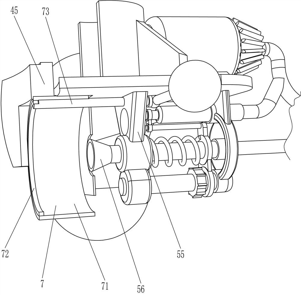
[0062] A kind of cylinder warning paint spraying equipment, such as figure 1 As shown, it includes an arc seat 1, a hinge plate 2, a fixing mechanism 3, a moving mechanism 4 and a spraying mechanism 5. A moving mechanism 4 is connected between the bottoms, a fixing mechanism 3 is connected between the arc seat 1 and the rear side of the hinge plate 2 , and a spraying mechanism 5 is connected on the moving mechanism 4 .
[0063] When people need to paint the warning pile, the fixing mechanism 3 is opened first, so that the arc seat 1 and the hinged plate 2 are separated, and then the device is stuck in the position that needs to be painted, and then the parts of the fixing mechanism 3 are blocked, so that The device is fixed on the warning pile, and then the paint is poured into the parts of the spraying mechanism 5, and the moving mechanism 4 and the parts of the spraying mechanism 5 are started, and the moving mechanism 4 drives the parts of the spraying mechanism 5 to spray ...
Embodiment 2
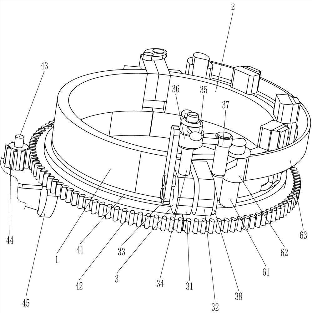
[0065] On the basis of Example 1, such as Figure 1-3As shown, the fixing mechanism 3 includes a first fixing plate 31, a second fixing plate 32, a limiting plate 33, a first screw rod 34, a first nut 35, a shaft sleeve 36, a fitting plate 37 and a wedge plate 38, and an arc seat 1 The rear side is connected with the first fixed plate 31, the rear side of the hinged plate 2 is connected with the second fixed plate 32, the left side of the second fixed plate 32 is connected with the wedge-shaped plate 38, and the first fixed plate 31 is slidably connected with the first screw 34. The right side of the first fixed plate 31 is connected with the limiting plate 33, the left side of the limiting plate 33 is slidably connected with a shaft sleeve 36, the first screw rod 34 is threadedly connected with a first nut 35, and the first nut 35 and the shaft sleeve The middle part of 36 is rotationally connected, and the left side of the axle sleeve 36 is connected with a mating plate 37, ...
Embodiment 3
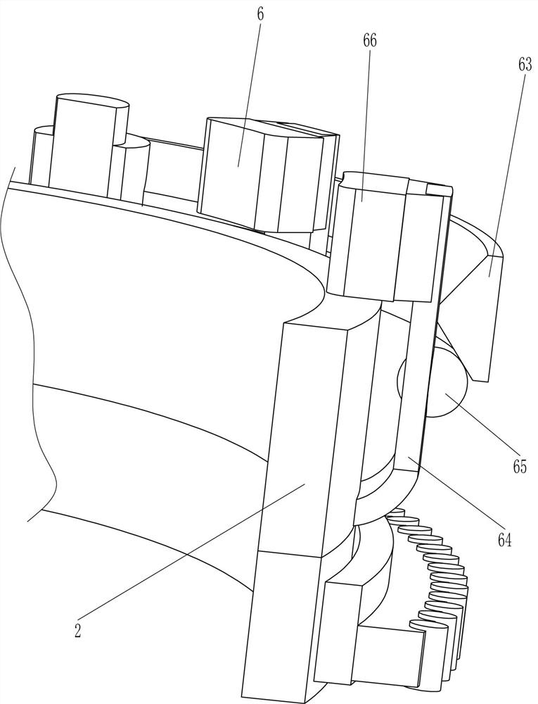
[0072] On the basis of Example 2, such as figure 2 , Figure 4 and Figure 5 As shown, it also includes a pressing mechanism 6, and the pressing mechanism 6 includes a guide rod 61, a matching sleeve 62, a trapezoidal plate 63, an elastic plate 64, a contact head 65 and a friction block 66, and the front and rear sides of the hinge plate 2 are connected with Guide rod 61, guide rod 61 is all connected with detachable matching sleeve 62, is connected with trapezoidal plate 63 between matching sleeve 62, and the matching sleeve 62 of rear side is detachably connected with matching plate 37, and the left side of hinge plate 2 is evenly connected with The elastic plate 64 and the top of the elastic plate 64 are connected with a friction block 66, the friction block 66 is attached to the top of the hinge plate 2, and the outer side of the elastic plate 64 is provided with a contact head 65, and the contact head 65 and the trapezoidal plate 63 are extrusion-fitted.
[0073] When ...
PUM
 Abstract
Description
Claims
Application Information
 - R&D
- Intellectual Property
- Life Sciences
- Materials
- Tech Scout
- Unparalleled Data Quality
- Higher Quality Content
- 60% Fewer Hallucinations
Browse by: Latest US Patents, China's latest patents, Technical Efficacy Thesaurus, Application Domain, Technology Topic, Popular Technical Reports.
© 2025 PatSnap. All rights reserved.Legal|Privacy policy|Modern Slavery Act Transparency Statement|Sitemap|About US| Contact US: help@patsnap.com


