

Pipeline inner wall spraying reciprocating machine
A reciprocating machine and pipeline technology, which is applied in the field of reciprocating machine spraying on the inner wall of the pipeline, can solve the problems of low work efficiency, blockage of the spray pipe, long replacement time, etc., and achieve the effect of convenient replacement and improved work efficiency
- Summary
- Abstract
- Description
- Claims
- Application Information
AI Technical Summary
Problems solved by technology
Method used
Image

Examples
Embodiment 1
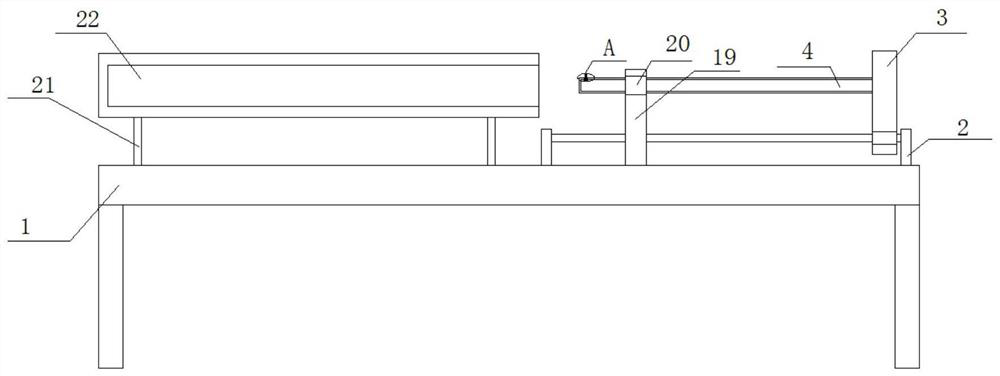
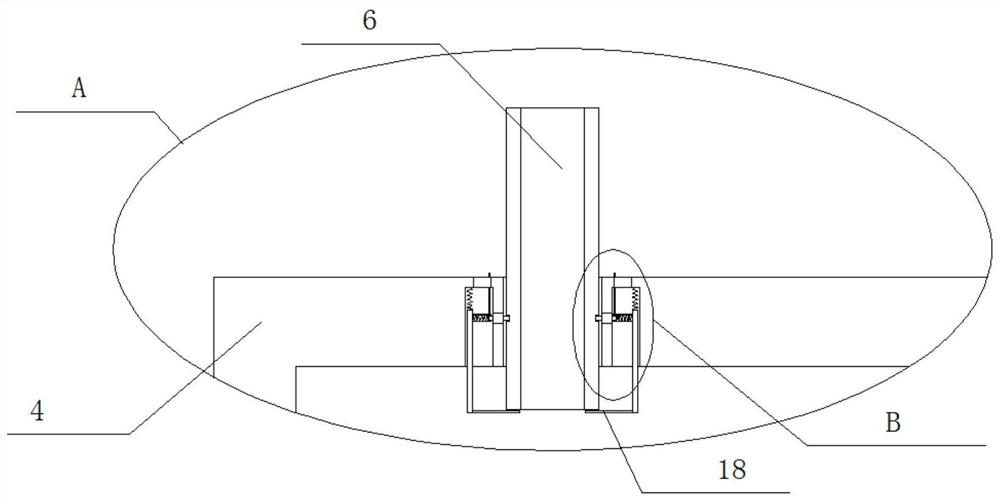
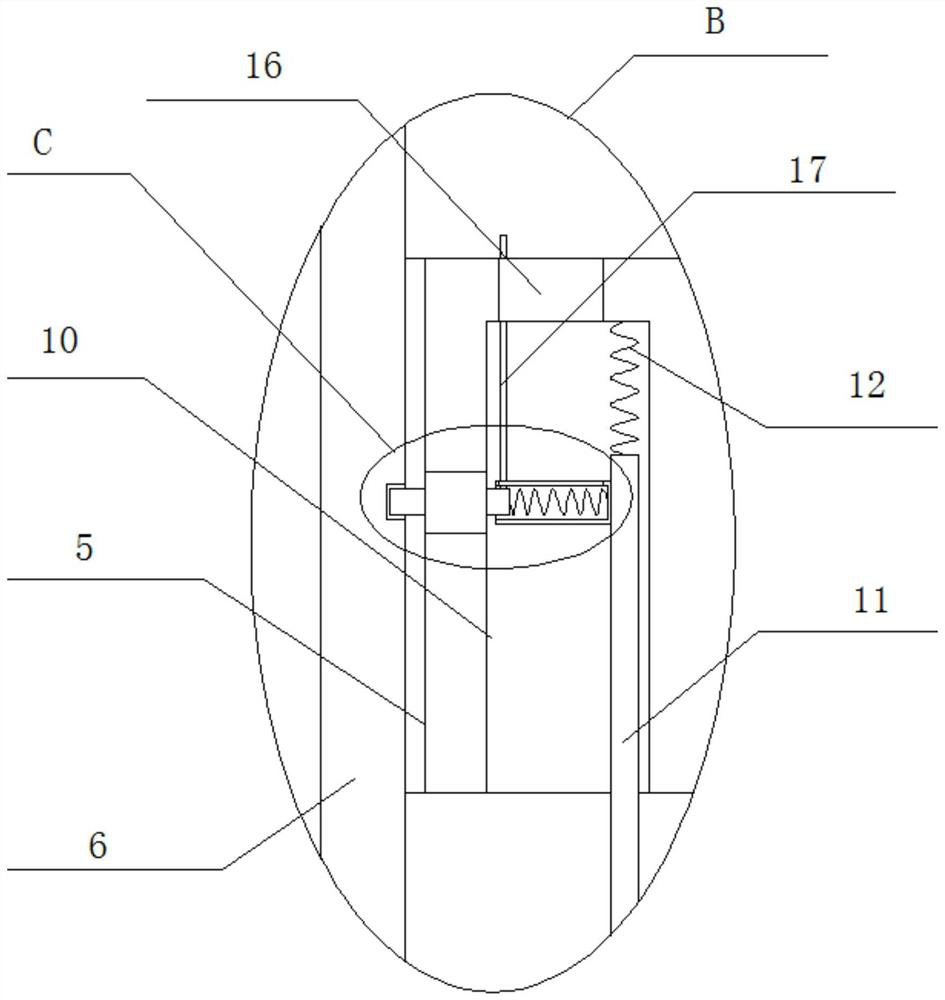
[0022] refer to Figure 1-3 , a reciprocating machine for spraying the inner wall of a pipeline, including a workbench 1, a slide rail 2 is fixedly installed on one side of the top of the workbench 1, a console 3 is slidably installed on the slide rail 2, and a connection is fixedly installed on one side of the console 3 Pipe 4, the top of the connecting rod 4 is provided with a fixed hole 5 on the inner wall of the side away from the console 3, and the spray pipe 6 is movably installed in the fixed hole 5, and the inner wall of the side far away from the console 3 is provided with a concave Groove 10, limit hole 7 is offered on the both sides inner walls of fixing hole 5, limit groove 8 is all set on both sides of material spray pipe 6, limit rod 9 is slidably installed in limit hole 7, and one end of limit rod 9 extends To the limiting groove 8, the other end of the limiting rod 9 extends into the groove 10, the limiting rod 9 is used for fixing, and the spray pipe 6 is used...
Embodiment 2
[0029] A reciprocating machine for spraying the inner wall of a pipeline, including a workbench 1, a slide rail 2 is fixedly welded and installed on one side of the top of the workbench 1, a console 3 is slidably installed on the slide rail 2, and a connecting pipe is fixedly welded on one side of the console 3 4. A fixed hole 5 is chiseled on the inner wall of the side away from the console 3 at the top of the connecting rod 4, and a spray pipe 6 is installed in the fixed hole 5, and a groove is chiseled on the inner wall of the side far away from the console 3 at the top of the connecting rod 4 10. Limiting holes 7 are drilled on the inner walls of both sides of the fixing hole 5, limiting grooves 8 are drilled on both sides of the spray pipe 6, and limiting rods 9 are slidably installed in the limiting holes 7, and one end of the limiting rods 9 extends to In the limiting groove 8 , the other end of the limiting rod 9 extends into the groove 10 .
[0030] In the present inv...
PUM
 Abstract
Description
Claims
Application Information