Inclined rail numerical control lathe

A technology of CNC lathes and inclined rails, which is applied in the field of CNC lathes, can solve the problems of wear and loosening, affecting the sliding and acceleration of the seat body, and achieve the effect of avoiding overfilling and preventing friction.

Inactive Publication Date: 2020-12-18
陈劲毅
View PDF0 Cites 2 Cited by
  • Summary
  • Abstract
  • Description
  • Claims
  • Application Information

AI Technical Summary

Problems solved by technology

[0003] When the inclined rail CNC lathe is working, iron filings and dust will still fall on the inclined rail, which will affect the sliding of the seat body on the inclined rail and easily accelerate the wear and loosening between the two

Method used


Image

  • Inclined rail numerical control lathe
  • Inclined rail numerical control lathe
  • Inclined rail numerical control lathe

Examples


Embodiment 1

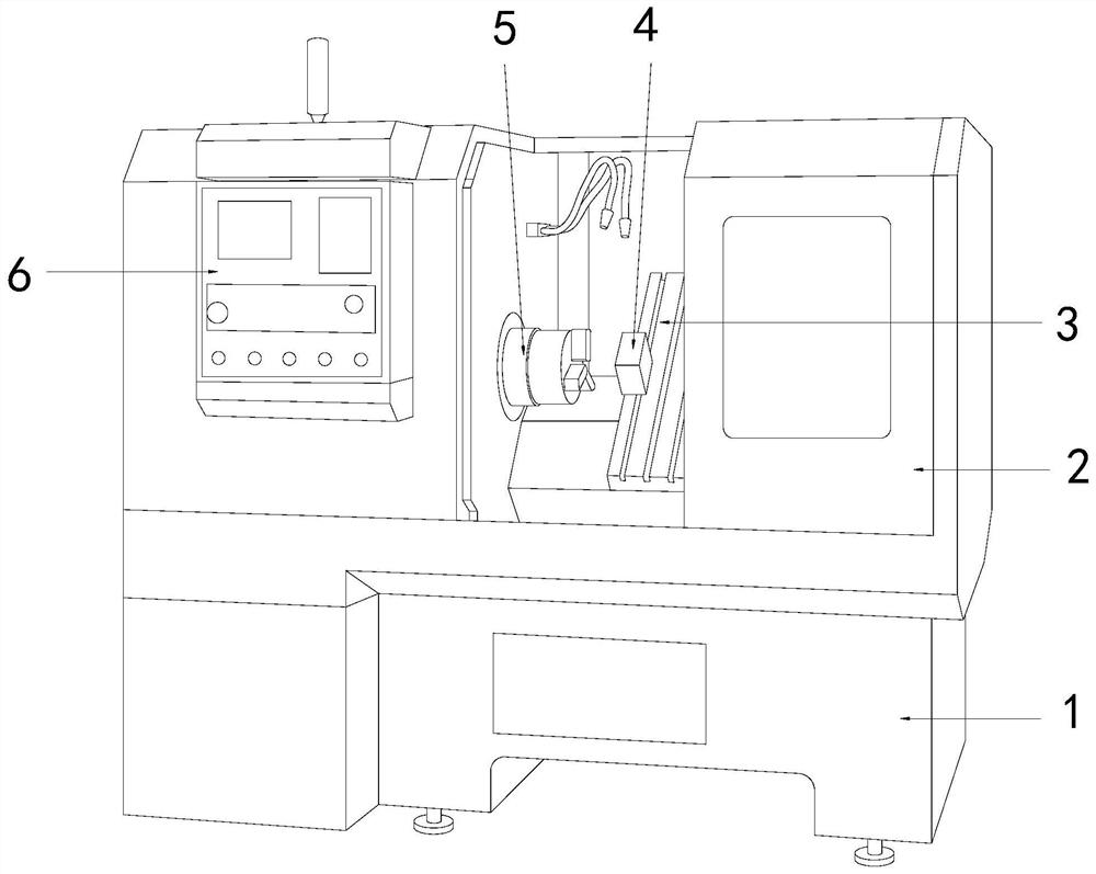
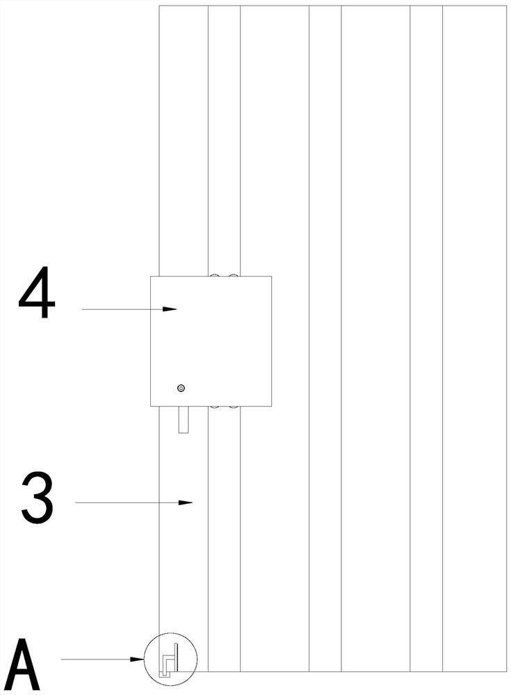
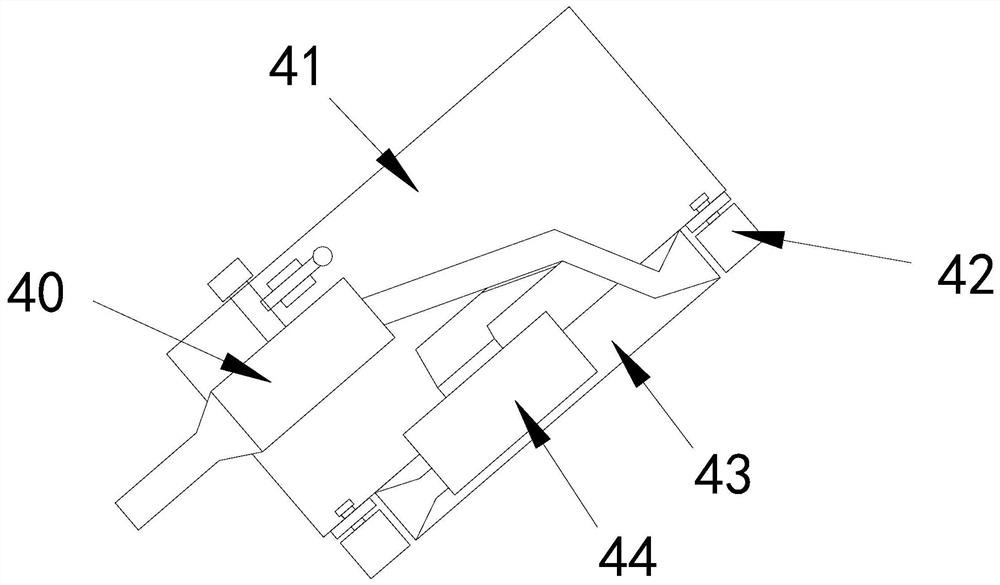
[0032] see Figure 1-8 , The present invention provides a technical scheme of a CNC lathe with inclined rail: its structure includes a base 1, a work box 2, an inclined guide rail 3, a clamp seat 4, a tool rest 5, and a controller 6, and the base 1 is connected with a work box 2, A controller 6 is connected to the outside of the work box 2, and a tool holder 5 and an inclined guide rail 3 are respectively installed on the left and right sides of the inside of the work box 2. A clamp seat 4 is installed on the inclined guide rail 3, and the clamp base 4 includes a set Dust structure 40, seat 41, cleaning wheel 42, slider 43, fan 44, the bottom of the seat 41 is provided with a slider 43 and the two are an integrated structure, the two ends of the slider 43 are respectively provided with cleaning The cleaning wheel 42 is installed at the bottom of the seat body 41. The seat body 41 is provided with a dust collecting structure 40, and the dust collecting structure 40 is communica...

Embodiment 2

[0035] see Figure 1-10, The present invention provides a technical scheme of a CNC lathe with inclined rail: its structure includes a base 1, a work box 2, an inclined guide rail 3, a clamp seat 4, a tool rest 5, and a controller 6, and the base 1 is connected with a work box 2, A controller 6 is connected to the outside of the work box 2, and a tool holder 5 and an inclined guide rail 3 are respectively installed on the left and right sides of the inside of the work box 2. A clamp seat 4 is installed on the inclined guide rail 3, and the clamp base 4 includes a set Dust structure 40, seat 41, cleaning wheel 42, slider 43, fan 44, the bottom of the seat 41 is provided with a slider 43 and the two are an integrated structure, the two ends of the slider 43 are respectively provided with cleaning The cleaning wheel 42 is installed at the bottom of the seat body 41. The seat body 41 is provided with a dust collecting structure 40, and the dust collecting structure 40 is communica...


PUM


Abstract

The invention discloses an inclined rail numerical control lathe. The inclined rail numerical control lathe structurally comprises a base, a working box, an inclined guide rail, a clamp seat, a tool rest and a controller, wherein the working box is connected to the base, the controller is connected to the outer side of the working box, the tool rest and the inclined guide rail are installed on theleft side and the right side in the working box correspondingly, and the clamp seat is installed on the inclined guide rail; and the clamp base comprises a dust collecting structure, a seat body, sweeping wheels, a sliding block and a draught fan, wherein the sliding block is arranged at the bottom of the seat body and integrated with the seat body, the sweeping wheels are arranged at the two ends of the sliding block correspondingly, the sweeping wheels are installed at the bottom of the seat body, and the dust collecting structure is arranged in the seat body and communicates with the draught fan. The inclined rail numerical control lathe has the beneficial effects that scrap iron and dust can be swept away when an air inlet pipe and an air outlet pipe of the draught fan move on the inclined rail, friction between the inclined rail and the seat body is avoided, collected dust can be automatically cleaned away, the dust collecting position is prevented from being full of the dust, the sweeping wheels can automatically rotate through friction plates, and additional power is not needed.

Description

technical field [0001] The invention relates to the field of numerical control lathes, in particular to an inclined rail numerical control lathe. Background technique [0002] Inclined rail CNC lathe is a high-precision, high-efficiency automatic machine tool. Equipped with a multi-station turret or a power turret, the machine tool has a wide range of technological performance, which can process linear cylinders, oblique cylinders, arcs and various threads, grooves, worms and other complex workpieces. Compensate various compensation functions, and play a good economical effect in the mass production of complex parts. [0003] When the inclined rail CNC lathe is working, the iron filings and dust will still fall on the inclined rail, which will affect the sliding of the seat on the inclined rail and easily accelerate the wear and loosening between the two. SUMMARY OF THE INVENTION [0004] The main purpose of the present invention is to overcome the deficiencies of the pr...

Claims


Application Information

Patent Timeline
Patent Type & Authority Applications(China)
IPC IPC(8): B23B7/14B23Q11/00
CPCB23B7/12B23Q11/005
Inventor 陈劲毅
Owner 陈劲毅
Why Eureka
Try Eureka