Automatic feeding type new energy automobile production line

A new energy vehicle, automatic feeding technology, applied in the direction of motor vehicles, transportation and packaging, etc., can solve the problems of high use limitations, poor adaptability of skids, etc., to increase support stability, reduce use limitations, improve adjustment convenience effect

Pending Publication Date: 2020-12-18
YANCHENG INST OF TECH
View PDF7 Cites 0 Cited by
  • Summary
  • Abstract
  • Description
  • Claims
  • Application Information

AI Technical Summary

Problems solved by technology

[0002] As we all know, an automatic feeding new energy automobile production line is an auxiliary device for automatic feeding of new energy automobile production lines, which has been widely used in the field of automobile production; an existing automatic feeding type During the use of the new energy vehicle production line, it was found that the combined skid commonly used in the painting workshop can support 8 types of vehicle models. The size, material and precision of the skid need to be designed according to the requirements of different vehicle models and the structural layout of the workshop. The skid is divided into two front fulcrums and six rear fulcrums. Different models correspond to different combinations of fulcrums. As the replacement of cars is getting faster and faster, when the body is widened and elongated, and the model changes significantly, the sled's The outer width and height need to be redesigned to meet the support requirements of different models, so the original skid cannot adapt to multiple needs, resulting in poor adaptability and high use limitations

Method used


Image

  • Automatic feeding type new energy automobile production line
  • Automatic feeding type new energy automobile production line
  • Automatic feeding type new energy automobile production line

Examples


Embodiment Construction

[0018] The specific implementation manners of the present invention will be further described in detail below in conjunction with the accompanying drawings and embodiments. The following examples are used to illustrate the present invention, but are not intended to limit the scope of the present invention.

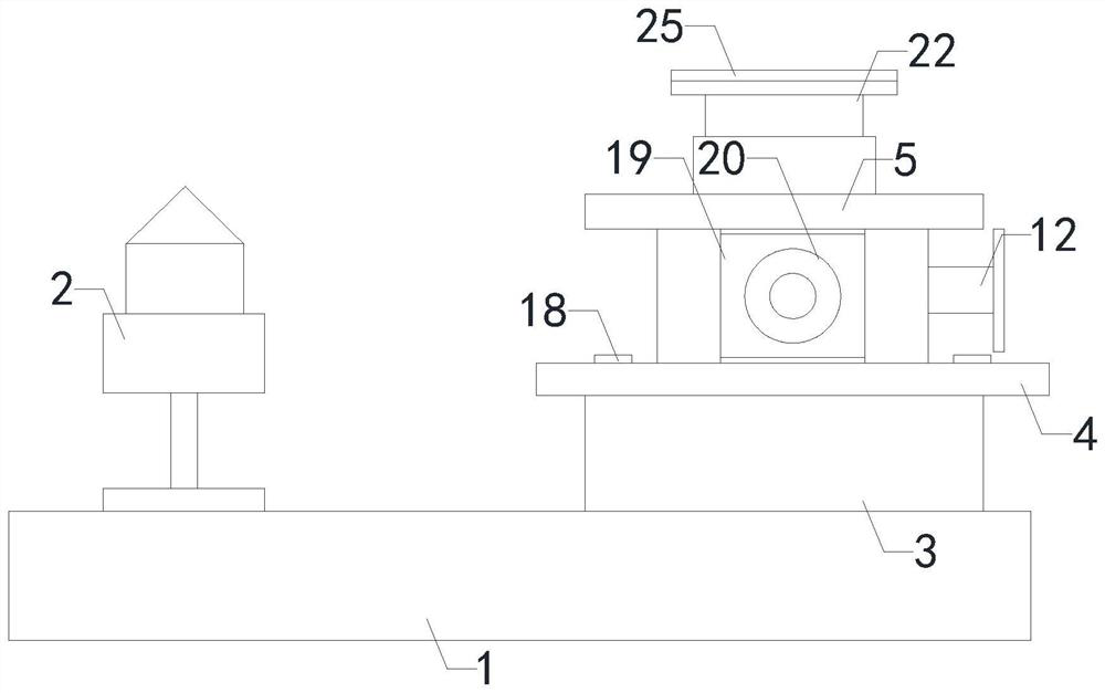
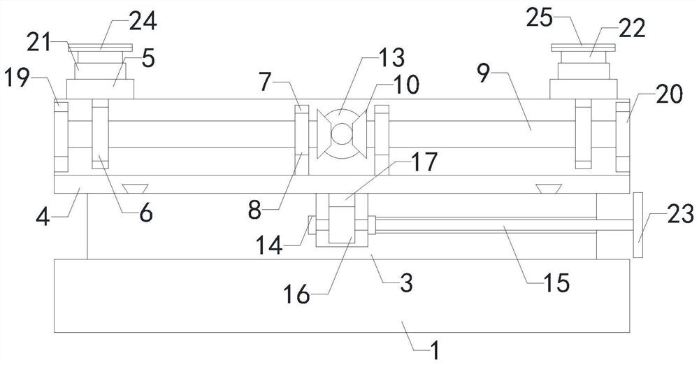
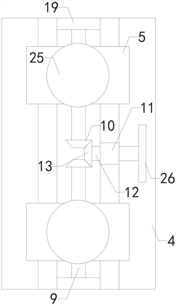
[0019] like Figure 1 to Figure 4 As shown, an automatic feeding type new energy automobile production line of the present invention includes a skid body 1, a front fulcrum 2, a first support frame 3, a second support frame 4, a rear bracket 5, a threaded sleeve 6, and a connecting frame 7. The first bearing 8, the lead screw 9, the driven conical gear 10, the longitudinal adjustment shaft 12 and the driving bevel gear 13, the bottom end of the front fulcrum 2 is installed on the left side of the top of the skid body 1, and the first support frame 3 The bottom end is installed on the right side of the top of the skid body 1, the bottom end of the second support frame 4 is...


PUM


Abstract

The invention relates to the technical field of automobile production, in particular to an automatic feeding type new energy automobile production line. The automatic feeding type new energy automobile production line improves the adaptability of a device to the automobile body size, improves the adjustment convenience, improves the supporting stability, improves the operability and reduces the use limitation. The automatic feeding type new energy automobile production line comprises a skid body, a front supporting point, a first supporting frame, a second supporting frame, a rear bracket, a threaded sleeve, a connecting frame, first bearings, lead screws, driven conical gears, a longitudinal adjusting shaft and a driving conical gear. The bottom end of the front supporting point is installed on the left side of the top end of the skid body in a matched mode, the bottom end of the second supporting frame is installed at the top end of the first supporting frame, the threaded sleeve isinstalled in a through hole of a connecting piece at the bottom of the rear bracket, the lead screws are coaxially matched and rotatably connected with the first bearings, the driven conical gears aresymmetrically and coaxially installed at the adjacent ends of the two lead screws, the first bearings are installed in supporting arm shaft holes in the right side of the second supporting frame, thelongitudinal adjusting shaft is coaxially matched and rotatably connected with the first bearings, and the right end of the driving conical gear is coaxially connected with the left end of the longitudinal adjusting shaft.

Description

technical field [0001] The invention relates to the technical field of automobile production, in particular to an automatic feeding type new energy automobile production line. Background technique [0002] As we all know, an automatic feeding new energy automobile production line is an auxiliary device for automatic feeding of new energy automobile production lines, which has been widely used in the field of automobile production; an existing automatic feeding type During the use of the new energy vehicle production line, it was found that the combined skid commonly used in the painting workshop can support 8 types of vehicle models. The size, material and precision of the skid need to be designed according to the requirements of different vehicle models and the structural layout of the workshop. The skid is divided into two front fulcrums and six rear fulcrums. Different models correspond to different combinations of fulcrums. As the replacement of cars is getting faster an...

Claims


Application Information

Patent Timeline
IPC IPC(8): B62D65/18
CPCB62D65/18
Inventor 郑竹安石小龙熊新郭大宏肖海宁张炯
Owner YANCHENG INST OF TECH
Why Eureka
Try Eureka