Floating buffer hydraulic oil cylinder for crane

A technology of hydraulic cylinders and cranes, which is applied in the field of buffer hydraulic cylinders and can solve problems such as time-consuming, laborious and tedious

Inactive Publication Date: 2020-12-18
江苏昊阳传动科技有限公司
View PDF0 Cites 0 Cited by
  • Summary
  • Abstract
  • Description
  • Claims
  • Application Information

AI Technical Summary

Problems solved by technology

[0005] However, the existing floating buffer hydraulic cylinders used for cranes are regularly repaired by adding lubricating oil, which requires manual disassembly and replacement, which is cumbersome and time-consuming.

Method used


Image

  • Floating buffer hydraulic oil cylinder for crane
  • Floating buffer hydraulic oil cylinder for crane
  • Floating buffer hydraulic oil cylinder for crane

Examples


Embodiment 1

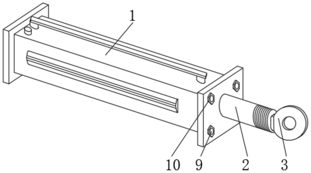
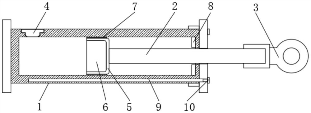
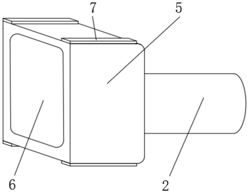
[0047] see Figure 1-9 , a floating buffer hydraulic cylinder for cranes, including a hydraulic cylinder body 1, a piston rod 2 is slidably connected to the inside of the hydraulic cylinder body 1, a piston 5 is fixedly installed on the left end of the piston rod 2, and a piston 5 is fixedly installed on the left upper end of the hydraulic cylinder body 1. An oil seal port 4 is installed embedded, a plug core 6 is arranged inside the piston 5, a guide block 7 is fixedly installed on the outer surface of the piston 5, a seal 8 is arranged inside the right side of the hydraulic oil cylinder body 1, and the right end of the hydraulic oil cylinder body 1 An oil seal port 10 is provided, an oil storage pipe 9 is connected to the left side of the oil seal port 10, a condensation ball 11 is connected to the inside of the oil storage pipe 9, an oil storage bag 12 is arranged on the inside of the condensation ball 11, and an oil storage bag 12 is connected to the inside of the oil stora...


PUM


Abstract

The invention discloses a floating buffer hydraulic oil cylinder for a crane, and belongs to the field of buffer hydraulic oil cylinders. The floating buffer hydraulic oil cylinder for the crane is characterized in that heat generated by friction between a piston and the interior of a cylinder body is conducted into an oil storage bag, the solid lubricating oil inside the oil storage bag is melted, so that generated lubricating oil liquid quantitatively secretes the lubricating oil to the joint of the piston and the cylinder body in skin sweat secretion imitating mode, so that a quantitative lubricating effect is achieved, a lubricating effect is achieved conveniently, and in the lubricating oil secreting process, due to the change of hole pressure, through the arranged one-way throttle pipe, a first deformation block and a second deformation block which are arranged at the ends of the one-way throttle pipe circulate from top to bottom and are in a closed state from bottom to top, theinternal lubricating condition can be conveniently changed in a one-way mode, normal operation of lubrication can be effectively guaranteed, and in addition, the stability of the pressure intensity inside the cylinder body is not affected.

Description

technical field [0001] The invention relates to the field of buffer hydraulic oil cylinders, in particular to a floating buffer hydraulic oil cylinder for cranes. Background technique [0002] A crane refers to a multi-action hoisting machine that lifts vertically and carries heavy objects horizontally within a certain range. One of the important components of the crane is the hydraulic cylinder. The hydraulic cylinder is an energy conversion device that converts hydraulic energy into mechanical energy for reciprocating linear motion. A hydraulic cylinder generally includes a cylinder barrel, a cylinder bottom, a cylinder top, a piston rod and a piston, wherein the cylinder bottom and the cylinder top are respectively provided at the bottom and top two outlets of the cylinder barrel, and the first end of the piston rod (the extension end) The piston is movably arranged in the cylinder, the second end of the piston rod is located outside the cylinder top, the first end of the...

Claims


Application Information

Patent Timeline
Patent Type & Authority Applications(China)
IPC IPC(8): F15B15/14F15B15/20F16N7/12F16N19/00F16N21/04F16N21/06F16N39/02F16N39/04
CPCF15B15/1423F15B15/1428F15B15/1447F15B15/1471F15B15/1485F15B15/20F16N7/12F16N19/00F16N21/04F16N21/06F16N39/02F16N39/04
Inventor 周建伟
Owner 江苏昊阳传动科技有限公司
Why Eureka
Try Eureka