Reactive free radical generation system and working method thereof

A technology for generating systems and free radicals, applied in separation methods, chemical instruments and methods, water/sludge/sewage treatment, etc., can solve the problem of increasing energy consumption and production costs, unable to produce active free radical oxidation effects, and narrow application scope and other problems, to achieve the effect of simple design, convenient use and improved processing efficiency

Inactive Publication Date: 2017-11-24
傅国琳
View PDF8 Cites 0 Cited by
  • Summary
  • Abstract
  • Description
  • Claims
  • Application Information

AI Technical Summary

Problems solved by technology

This type of device has a narrow application range, and the exhaust gas must be mixed with ozone under the light source. The system itself cannot generate a large number of active free radicals to achieve the best oxidation effect, resulting in increased energy consumption and production costs.

Method used


Image

  • Reactive free radical generation system and working method thereof
  • Reactive free radical generation system and working method thereof
  • Reactive free radical generation system and working method thereof

Examples


Embodiment 1

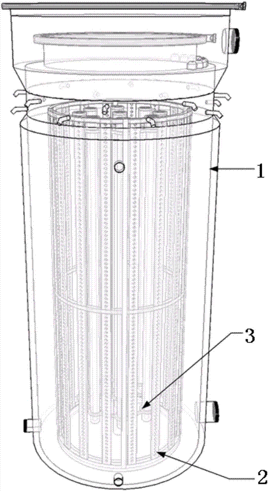
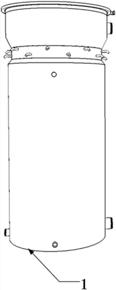
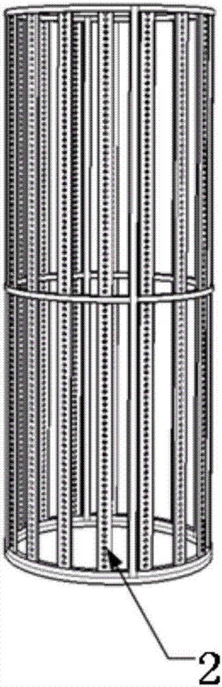
[0071] Example 1: figure 1 It is an embodiment of an active free radical generating system of the present invention, which includes: a main reaction chamber 1, an internal catalyst carrier system 2, installed in a cylindrical design structure composed of a catalyst carrier rod and a frame, and an ultraviolet lamp system 3. Comprising UV lamps 3.2 and a support for each lamp. The internal components of the ultraviolet lamp 3.2 (see FIG. 5 ) as shown in the drawings and accompanying drawings do not belong to the present invention, but are only used to demonstrate how this embodiment is used for fixing ultraviolet lamps and other similar lamps. The design of the present invention is shown as cylindrical, but it can also be designed as square, or hexagonal, and any other shape, and is not limited to cylindrical, square and hexagonal. The size, length, thickness and quantity contained in this embodiment can be changed according to actual needs.

[0072] Figure 2-1 , Figure 2-...

Embodiment 2

[0080] Example 2: Figure 7 It is the second embodiment of an active free radical generating system of the present invention. The ultraviolet lamp 3.2 is placed in the quartz tube 3.3, and the quartz tube 3.3 is installed in the main reaction chamber 1 for exciting and generating free radicals in the reaction chamber. The quartz tube 3.3 is made of quartz that can transmit 100% ultraviolet light to ensure the maximum effect of the light. There is an inlet 1.4 at the bottom of the present invention, which is used for ozone or other gases required for free radical generation reactions. There is a gas outlet 1.5 at the top of the main reaction chamber 1, which is used to release free radicals and gases generated by the reaction. The schematic design shows one exit, but multiple exits can be designed upon request. This outlet has an in-line check valve 1.5.1 to prevent back flow of gas or liquid. Figure 7 Also shown is a protective cover 1.11 on the top, which is used to prot...


PUM


Abstract

The invention relates to a reactive free radical generation system, which comprises a main reaction chamber and a light source system, wherein the light source system is arranged in the main reaction chamber, and the main reaction chamber is provided with an inlet for inputting gases and liquids required by a reaction and gas outlets. According to the present invention, the design is simple, and the use is convenient; the design steps are simple, the application range is wide, and any systems requiring reactive oxygen free radicals can use the reactive free radical generation system; ozone is irradiated by an ultraviolet lamp to produce a large amount of reactive oxygen free radicals, such that the oxidation efficiency is improved, the energy consumption is effectively reduced, and the cost is saved; and through the design of the gas outlet, the generated reactive oxygen free radical can contact the gas-phase pollutants such as nitrogen oxides or organic volatiles and the like in the main gas flow pipeline within 0.1 s, and the free radical intermediate generated after the chain reaction can be prevented from the exposure to the ultraviolet lamp.

Description

(1) Technical field: [0001] The invention relates to a system with simple design, convenient use, wide application range, large output of active free radicals, safe operation, more energy saving and environmental protection compared with traditional devices, and low cost, suitable for producing a large amount of active free radicals and its working method. (two) background technology: [0002] At present, free radical oxidation technology, as a new treatment technology, has been applied in various industries and has broad prospects. In the treatment of waste water and waste gas, nitrogen oxides and organic pollutants in waste water or waste gas can be oxidized into CO in a short time 2 , N 2 And water and other non-toxic small molecule compounds, the removal effect of COD and bacteria in water is obvious, and there is no secondary pollution. There are few types of free radical generators on the market, and the general structure is complex, or the concentration of free radi...

Claims


Application Information

Patent Timeline
Patent Type & Authority Applications(China)
IPC IPC(8): B01J19/12B01D53/86B01D53/66B01D53/68B01D53/44B01D53/56C02F1/78C02F1/32
CPCB01D53/007B01D53/8631B01D53/8659B01D53/8675B01D53/8687B01D2255/1026B01D2255/2073B01D2255/20761B01D2255/20769B01D2255/802B01D2259/804B01J19/12B01J19/123C02F1/32C02F1/72C02F1/725C02F1/78Y02W10/37
Inventor 傅国琳拉胡尔苟帕拉张艳红栾昕
Owner 傅国琳
Why Eureka
Try Eureka