Texturing machine

A deformation machine, stretching deformation technology, applied in the direction of control of generators, motor generators, electromechanical brakes, etc., can solve the problems of inability to realize closed-loop control, high cost, and inability to control each processing point separately, so as to reduce the speed Monitor costs and reduce the effect of feedback bias

Inactive Publication Date: 2014-06-04
WUXI HONGYUAN ELECTROMECHANICAL TECH
View PDF7 Cites 6 Cited by
  • Summary
  • Abstract
  • Description
  • Claims
  • Application Information

AI Technical Summary

Problems solved by technology

[0003] The first solution is that a driving device drives multiple operating points to rotate synchronously through the transmission shaft, so as to realize the drafting, conveying, deformation and winding of each processing point. The disadvantage of this solution is that each processing point cannot be controlled separately. It is an integral transmission, which cannot realize the start and stop of a single operating point;
[0004] The second scheme is to drive each operation unit in the processing point through a separate drive, and the separate drive of the adjacent processing point is driven by a group of frequency converters, and the power supply between the separate drive and the frequency converter is switched on and off to realize the individual drive This solution solves the disadvantage that a single operating point cannot be started and stopped independently in the first solution. However, since a group of inverters drives multiple individual transmissions, it is impossible to achieve closed-loop control of the speed of a single transmission. The speed of a single transmission Open-loop control can only be realized based on the frequency of the group of inverters. If the main control system wants to monitor the real-time speed of each drive, it is necessary to add a speed sensor for each individual drive. In the case of multiple processing positions, the cost is high

Method used


Image

  • Texturing machine
  • Texturing machine
  • Texturing machine

Examples


Embodiment

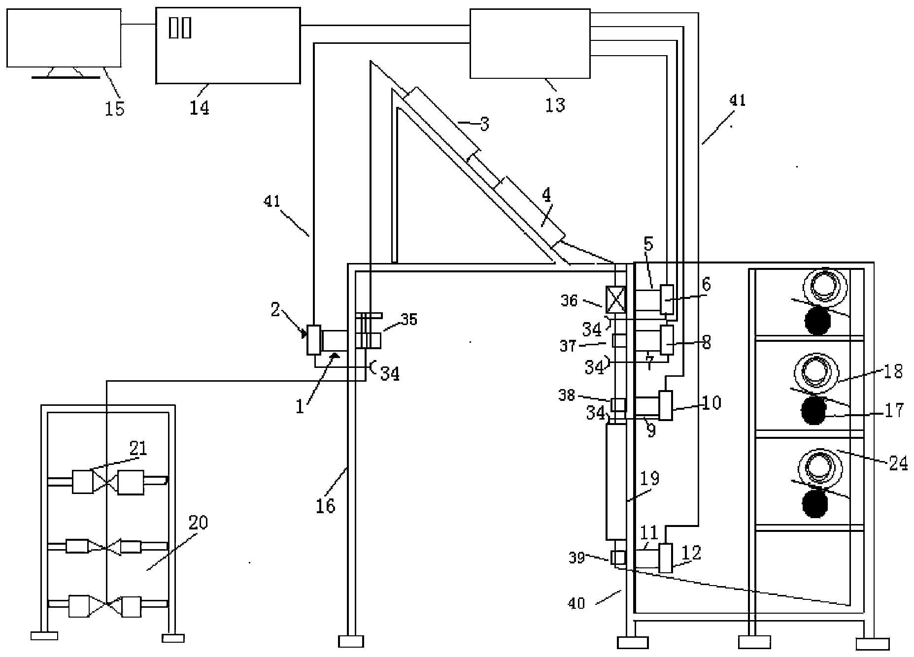
[0021] Example: such as figure 1 As shown, the texturing machine includes a raw wire frame 20, a first drafting device 35, a heating device 3, a cooling device 4, a false twisting device 36, a second drafting device 37, a first conveying device 38, a second heating device 19, The second conveying device 39 and the winding device 24 . The first drafting device 35, the heating device 3, the cooling device 4, the false twisting device 36, the second drafting device 37, the first conveying device 38, the second heating device 19, and the second conveying device 39 are followed by the machine support 16 and the second conveying device 39. The main frame 40 supports. The filament is drawn out from the raw yarn bobbin 21 installed on the raw yarn rack 20, passes through the first drafting device 35, enters the first heating device 3 for heating, and the cooling device 4 cools down, and then is false twisted and deformed by the false twisting device 36, and enters the first drafting ...


PUM


Abstract

The invention discloses a texturing machine. The texturing machine comprises a plurality of machining spots, wherein the machining spots are in butt joint and are used for stretcher strain of filaments. Each machining spot is internally provided with a drafting, texturing and winding operation unit. At least one operation unit in each machining spot is provided with an independent transmitter of a motor. Each independent transmitter is provided with a driver and is composed of the motor of which a rotor is a permanent magnet with non-exciting current and a stator is a multi-phase winding. The drivers detect current of the multi-phase windings of the motors and calculate counter electromotive force voltage to obtain the position information of the rotors, and main controllers in communication with the drivers obtain the real-time speed of the motors through the position information of the rotors. The drivers can obtain detailed position information of the rotors while keeping high-speed and stable operation of the motors in a sensorless control mode, it is unnecessary to additionally arrange rotor position sensors or speed measurement sensors, feedback deflection caused by installation angles of the sensors or changes of environment temperature is reduced, the rotation speed of the independent transmitters can be monitored in real time, and closed-loop control can be achieved through speed feedback.

Description

technical field [0001] The invention relates to the field of textile machinery, in particular to a texturing machine. Background technique [0002] In order to draft and deform multiple filaments, the texturing machine has corresponding multiple processing points. Each processing point includes several working units, such as drafting unit, conveying device, false twist texturing unit and winding device, according to which the synthetic filament is drawn, textured and wound into a bobbin in the processing point. Two different solutions are known for driving the working group: [0003] The first solution is that a driving device drives multiple operating points to rotate synchronously through the transmission shaft, so as to realize the drafting, conveying, deformation and winding of each processing point. The disadvantage of this solution is that each processing point cannot be controlled separately. It is an integral transmission, which cannot realize the start and stop of...

Claims


Application Information

Patent Timeline
Patent Type & Authority Applications(China)
IPC IPC(8): D02G1/02H02P21/05
Inventor 缪小方孙斌张始荣付光怀孙明珠
Owner WUXI HONGYUAN ELECTROMECHANICAL TECH
Why Eureka
Try Eureka