Gateway equipment mounting and placing device

A technology for placing gateway equipment and placing boards, which is applied in the direction of mechanical equipment, electrical equipment components, supporting machines, etc., can solve the problems of affecting the performance of gateway equipment, unfavorable operation of gateway equipment, and poor heat dissipation effect, so as to improve the heat dissipation effect, Improving anti-seismic performance and avoiding damage

Inactive Publication Date: 2020-12-18
SUZHOU YAOKAI INFORMATION TECH CO LTD
View PDF0 Cites 3 Cited by
  • Summary
  • Abstract
  • Description
  • Claims
  • Application Information

AI Technical Summary

Problems solved by technology

The existing gateway equipment is usually installed in a placement device to protect it, but the gateway equipment will generate heat when it is working. The traditional gateway equipment placement device has a poor heat dissipation effect. Excessively high temperature has a certain negative impact on the performance of the gateway equipment. It is not conducive to the good work of the gateway equipment, and it is easy to affect the working performance of the gateway equipment

Method used


Image

  • Gateway equipment mounting and placing device
  • Gateway equipment mounting and placing device
  • Gateway equipment mounting and placing device

Examples


Embodiment Construction

[0028] In order to make the object, technical solution and advantages of the present invention clearer, the present invention will be further described in detail below in conjunction with the accompanying drawings and embodiments. It should be understood that the specific embodiments described here are only used to explain the present invention, not to limit the present invention.

[0029] The specific implementation of the present invention will be described in detail below in conjunction with specific embodiments.

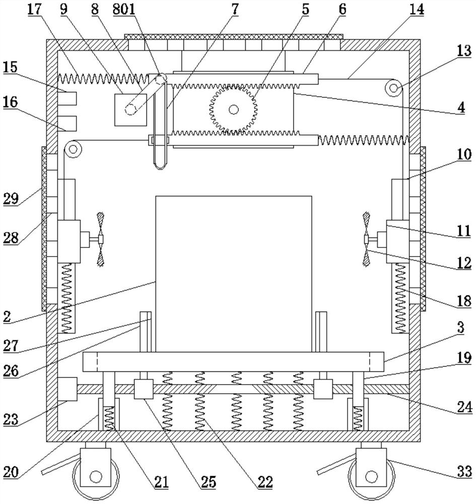
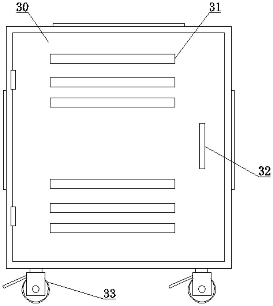
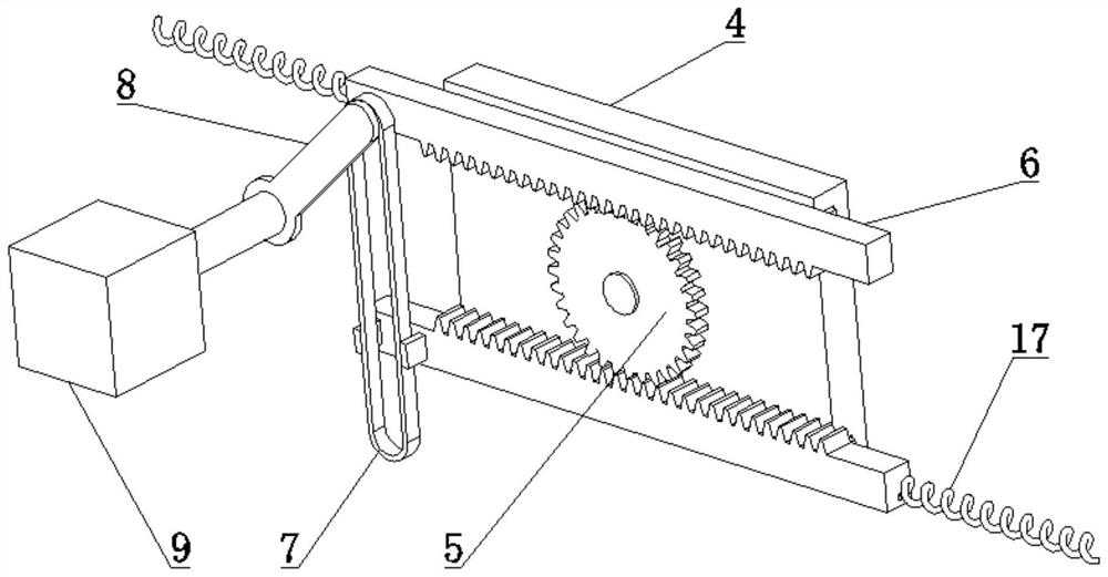
[0030] like Figure 1 to Figure 3 As shown, it is a structural diagram of a device for installing and placing gateway equipment provided by an embodiment of the present invention, including:

[0031] A housing 1, the inside of which is used to place a gateway device 2;

[0032] The sliding cavity 10 is fixedly installed on the side wall of the inner cavity of the housing 1, on which a slider 11 is slidably arranged;

[0033] A temperature sensor 15 is fixedly ...


PUM


Abstract

The invention is applicable to the technical field of computer gateway equipment, and provides a gateway equipment mounting and placing device. The gateway equipment mounting and placing device comprises a shell, sliding cavities, a temperature sensor, a processor and a fixed plate; the sliding cavities are fixed to the side walls of an inner cavity of the shell, and sliding blocks are slidably arranged on the sliding cavities; the temperature sensor is used for monitoring the internal temperature of the shell, and the processor is used for processing a temperature signal; the fixed plate is arranged at the top of the inner cavity of the shell, a gear is rotationally arranged on the fixed plate, the two sides of the gear are meshed with toothed plates, the toothed plates are arranged on the fixed plate in a sliding mode, and a sliding frame is fixed onto one toothed plate; a first power piece is fixed inside the shell, a connecting rod is fixed to an output shaft of the first power piece, and a boss is arranged at the end part of the connecting rod and is arranged in the sliding frame; and the two toothed plates are connected with the sliding blocks on the two sides of the inner cavity of the shell through connecting ropes correspondingly, fans are arranged on the sliding blocks, and pulleys are arranged inside the shell and are used for supporting the connecting ropes. According to the embodiment, the heat dissipation effect of gateway equipment can be improved, so that good work of the gateway equipment is facilitated.

Description

technical field [0001] The invention belongs to the technical field of computer gateway equipment installation, and in particular relates to a gateway equipment installation and placement device. Background technique [0002] Gateway devices, also known as internet connectors and protocol converters, are computer systems or devices that provide data conversion services between multiple networks. The gateway device repackages the received information to meet the needs of the destination system, and at the same time plays the role of filtering and security. The gateway device is an important network connection device and needs to be well protected. The existing gateway equipment is usually installed in a placement device to protect it, but the gateway equipment will generate heat when it is working. The traditional gateway equipment placement device has a poor heat dissipation effect. Excessively high temperature has a certain negative impact on the performance of the gateway...

Claims


Application Information

Patent Timeline
Patent Type & Authority Applications(China)
IPC IPC(8): F16M11/04F16M11/42F16F15/067H05K7/20
CPCF16F15/067F16M11/04F16M11/42H05K7/20136
Inventor 徐天元
Owner SUZHOU YAOKAI INFORMATION TECH CO LTD
Why Eureka
Try Eureka