A high air intake pipe air tightness detection device

A technology of air tightness detection and air intake pipe, which is applied in the direction of measuring device, liquid tightness measurement using liquid/vacuum degree, fluid tightness test, etc. It can solve the problems of cumbersome detection methods and expensive detection equipment, and achieve detection Good effect and accurate test results

Active Publication Date: 2021-02-02
山东艾泰克环保科技股份有限公司
View PDF8 Cites 0 Cited by
  • Summary
  • Abstract
  • Description
  • Claims
  • Application Information

AI Technical Summary

Problems solved by technology

[0003] Existing high-position intake pipes need to be tested for their sealing performance when they leave the factory. When testing the sealing performance of high-position intake pipes, many people are often required to complete the inspection. The detection methods are cumbersome and the detection equipment is expensive. Therefore, it is necessary to provide a Simple and fast detection device for convenient and fast detection of high intake pipes

Method used


Image

  • A high air intake pipe air tightness detection device
  • A high air intake pipe air tightness detection device
  • A high air intake pipe air tightness detection device

Examples


Embodiment 1

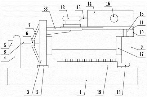
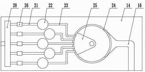
[0022] see Figure 1-4 , a high air intake pipe air tightness detection device, including a base 1, the two ends of the top of the base 1 are respectively fixedly connected to the fixed column 4 and the fixed seat 9, and the fixed column 4 is slidably connected to the sliding seat on the base 1 on the side close to the fixed seat 9 2. The top of the sliding seat 2 is fixedly connected to the moving frame 3, and the moving frame 3 is provided with a translation drive mechanism. The adjacent sides of the fixed seat 9 and the moving frame 3 are fixedly connected with a clamping seat 17, and the top of the fixed seat 9 is fixedly connected The top support frame 10, the top of the top support frame 10 is fixedly connected to the fixed top frame 11, the top of the fixed top frame 11 is fixedly connected to the partial pressure adjustment device, and one side of the partial pressure adjustment device is provided with an air compressor 12, the air compressor 12 The output end is fixed...

Embodiment 2

[0028] see Figure 1-4 , the other content of this embodiment is the same as that of Embodiment 1, except that the translational drive mechanism includes a first drive motor 5 fixedly connected to one side of the fixed post 4, and the output shaft of the first drive motor 5 is fixedly connected to drive The rod 8 and the driving rod 8 pass through the fixed column 4 and are rotationally connected with it. The outside of the driving rod 8 is sheathed and screwed to the moving sleeve 6 , and a plurality of fixed rods 7 are fixedly connected between the moving sleeve 6 and the fixed column 4 .

[0029] One side of the moving frame 3 is fixedly connected with a moving rail 33, and the moving rail 33 is located at the side of the moving top frame and is slidably connected with it.

[0030] In the implementation process of the present invention, the high air intake pipe is first placed between the two clamping seats 17, and then the first driving motor 5 is started to drive the movi...


PUM


Abstract

The invention discloses a high-position intake pipe airtightness detection device, which relates to the technical field of auto parts production, comprising a base, a translational drive mechanism is provided on a moving frame, and clamping seats are fixedly connected to the adjacent sides of the fixed seat and the moving frame , the top of the fixed seat is fixedly connected to the top support frame, the top of the top support frame is fixedly connected to the fixed top frame, the top of the fixed top frame is fixedly connected to the partial pressure adjustment device, and an air compressor is provided on one side of the partial pressure adjustment device. The output end of the output end is fixedly connected to the first air pipe, the second air pipe is fixedly connected between the partial pressure adjusting device and the air guiding channel, and the air guiding pipe is fixedly connected to the air pressure display device. For the air-tightness detection of the intake pipe, the air pressure display device can be used to display the air leakage of the high-position intake pipe, and it can also display the air leakage speed. The detection effect of the high-position intake pipe is good and the detection result is accurate.

Description

technical field [0001] The invention relates to the technical field of auto parts production, in particular to a high-position intake pipe airtightness detection device. Background technique [0002] The function of the air intake system is to provide the engine with clean, dry air at the proper temperature for combustion to minimize engine wear and maintain optimum engine performance. Therefore, the air intake system is required to have a high filtration efficiency to remove dust and moisture in the air. The high-position intake pipe assembly is the initial defense line of the automobile air intake system. Its function is to intake air at a high position to prevent impurities or dust in the low-position air from being sucked into the intake system, allowing clean air to enter the cylinder while reducing intake noise, so as to reduce the air intake of the cylinder and piston rings. wear and tear. [0003] Existing high-position intake pipes need to be tested for their seal...

Claims


Application Information

Patent Timeline
Patent Type & Authority Patents(China)
IPC IPC(8): G01M3/28
CPCG01M3/2815
Inventor 董翠梅
Owner 山东艾泰克环保科技股份有限公司
Why Eureka
Try Eureka