A hydrogen energy equipment testing system and testing method

A technology of equipment testing and testing methods, applied in mechanical equipment, piping systems, container filling methods, etc., can solve problems such as expensive helium, high testing costs, and inability to pressurize, so as to improve safety, reliability, and detection accuracy Sexuality, the effect of reducing the cost of using helium

Active Publication Date: 2022-04-29
河南氢枫能源技术有限公司 +1
View PDF0 Cites 0 Cited by
  • Summary
  • Abstract
  • Description
  • Claims
  • Application Information

AI Technical Summary

Problems solved by technology

[0002] With the continuous development of the hydrogen energy industry, the demand for equipment including hydrogenation machines, gas unloading cabinets, sequence control cabinets, and compressors is also increasing. Therefore, domestic hydrogen energy equipment manufacturers have sprung up. These hydrogen energy equipment Manufacturers can only conduct some simple tests in the factory, including pressure tests and power-on tests, but they cannot perform full-condition tests and linkage tests between devices, so many problems cannot be detected in the factory
[0003] In this case, when the hydrogen energy equipment arrives at the project site for debugging, there will still be various problems such as inability to realize hydrogenation, inability to pressurize, and internal leakage of electric valves. Therefore, hydrogen energy equipment needs to be installed before installation. In the existing technology, hydrogen detection will be used for equipment assembly, but when it comes to safety issues, it is a better choice to use inert gas simulation. The molecular weight of helium is small, and the detection results are more accurate, which is better than nitrogen. Detection, because the hydrogen energy equipment is relatively large, the price of helium is expensive, and the detection cost is high

Method used


Image

  • A hydrogen energy equipment testing system and testing method

Examples


Embodiment Construction

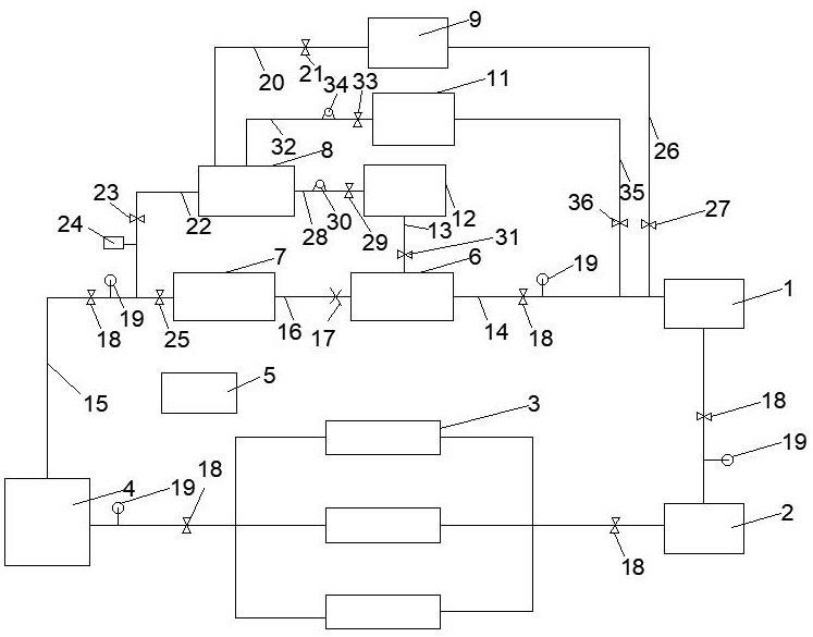
[0029] The following are specific embodiments of the present invention and in conjunction with the accompanying drawings, the technical solutions of the present invention are further described, but the present invention is not limited to these embodiments.

[0030] like figure 1 As shown, a hydrogen energy equipment testing system of the present invention, the equipment to be tested includes an unloading cabinet 1 connected in series through a main pipe, a compressor 2, a hydrogen storage bottle group 3, and a hydrogenation machine 4, and the testing system includes a control system 5, a helium Gas supply bottle 6, helium filling bottle 7, magnesium-based hydrogen storage tank 8, hydrogen supply bottle 9, nitrogen storage device 11 and helium storage device 12; helium storage device 12 supplies helium gas through helium supply pipe 13 The gas cylinder 6 supplies gas, the helium gas supply cylinder 6 communicates with the gas unloading cabinet 1 through the second connecting pi...


PUM


Abstract

The invention discloses a hydrogen energy equipment testing system and testing method. The test system uses helium as the test medium, and the helium storage device supplies gas to the test system. The gas unloading cabinet, compressor, hydrogen storage cylinder group, and hydrogenation machine are in working condition, and the helium gas passes through the helium gas supply cylinder and the gas unloading cabinet. , compressor, hydrogen storage bottle group, hydrogenation machine, helium filling bottle, and finally to the helium gas supply bottle to form a gas circuit cycle to realize the test of hydrogen energy equipment. The molecular weight of helium is small, and the test result is more accurate , which is superior to nitrogen detection. Through this system, not only can gas leakage detection be realized, but also helium can be recycled. After the detection is completed, hydrogen is used to drive out the helium in the detection system, and then the magnesium-based hydrogen storage tank is used to absorb the helium. Hydrogen in the mixed gas, then recover the helium, and then use nitrogen to drive out the hydrogen in the detection system, then use the magnesium-based hydrogen storage tank to absorb the hydrogen in the mixed gas, and then recover the nitrogen to improve the detection accuracy. The cost of using helium is greatly reduced.

Description

technical field [0001] The invention relates to the technical field of hydrogen energy equipment, in particular to a hydrogen energy equipment testing system and testing method. Background technique [0002] With the continuous development of the hydrogen energy industry, the demand for equipment including hydrogenation machines, gas unloading cabinets, sequence control cabinets, and compressors is also increasing. Therefore, domestic hydrogen energy equipment manufacturers have sprung up. These hydrogen energy equipment Manufacturers can only conduct some simple tests in the factory, including pressure tests and power-on tests, but they cannot conduct full-condition tests and linkage tests between devices, so many problems cannot be detected in the factory. [0003] In this case, when the hydrogen energy equipment arrives at the project site for debugging, there will still be various problems such as inability to realize hydrogenation, inability to pressurize, and internal ...

Claims


Application Information

Patent Timeline
Patent Type & Authority Patents(China)
IPC IPC(8): G01M3/28G01M99/00F17C5/06F17C7/00F17C11/00F17C13/00F17C13/02F17C13/04F17D5/00F17D5/02
CPCG01M3/2815G01M3/2876G01M99/005F17C5/06F17C7/00F17C11/005F17C13/00F17C13/04F17C13/025F17D5/02F17D5/005F17C2221/017F17C2221/012F17C2227/0157F17C2227/0302F17C2205/0352F17C2205/0388F17C2227/044Y02E60/32Y02P90/45
Inventor 方沛军宣锋殷小军姜方伍远安曹俊
Owner 河南氢枫能源技术有限公司
Why Eureka
Try Eureka