
Phase sequence self-adaption method based on transient wave recording type fault indicator

A fault indicator, self-adaptive technology, applied in the direction of phase sequence/synchronization indication, phase angle between voltage and current, instruments, etc. Requirements, convenient for workers to install, and the effect of reducing installation judgment time

Inactive Publication Date: 2020-12-18
QINGDAO TOPSCOMM COMM +1
View PDF2 Cites 5 Cited by
  • Summary
  • Abstract
  • Description
  • Claims
  • Application Information

AI Technical Summary

Problems solved by technology

However, the on-site installation situation is complex and changeable, and some on-site construction personnel do not clear the current direction of the line and the phase sequence of the line. On both sides, it eventually leads to the inability to correctly select the line when a fault occurs on site, which undoubtedly creates greater obstacles for fault judgment
Moreover, once an error occurs, it is extremely difficult to find and correct the error, which may lead to the wrong transient direction of the zero-sequence current at the time of the fault, and eventually lead to the failure of fault judgment and location
[0004] At present, phase sequence self-adaptation is mostly implemented by hardware circuits, such as full bridges, rectifiers, etc., but they all have a fatal shortcoming. The equipment must ensure that the power line is powered off before it can be connected to the power equipment, resulting in high power outage costs. and not easy to maintain

Method used


Image

  • Phase sequence self-adaption method based on transient wave recording type fault indicator
  • Phase sequence self-adaption method based on transient wave recording type fault indicator
  • Phase sequence self-adaption method based on transient wave recording type fault indicator

Examples


Embodiment Construction

[0019] In order to make the object, technical solution and advantages of the present invention clearer, the present invention is further described in detail. It should be understood that the specific embodiments described here are only used to explain the present invention, not to limit the present invention.

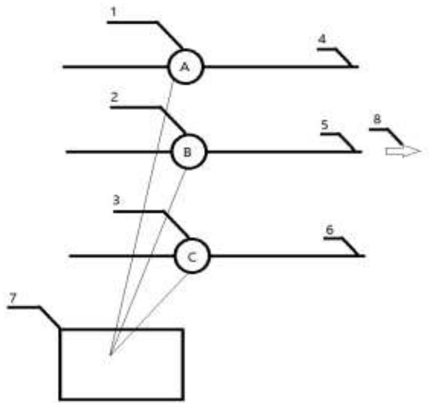
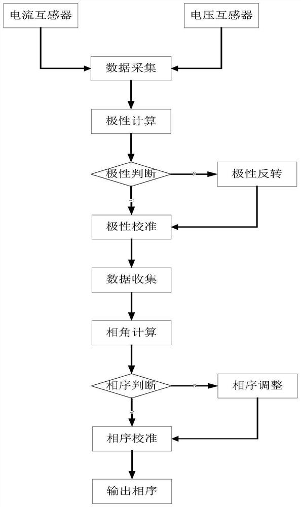
[0020] Such as figure 1 As shown, the host collection unit of the transient state recording type fault indicator first distinguishes the phase sequence of the line by networking the slave units of the three acquisition units. After the collection unit is networked with the collection unit, it will synchronize the time of the collection unit, and the collection unit will collect the current and voltage data of each overhead line synchronously to ensure that the current and electric field data of the three-phase sampling are synchronized at any time. The collection unit can send wave recording commands wirelessly, and the acquisition unit triggers wave recording at the s...


PUM


Abstract

The invention discloses a phase sequence adaptive method based on a transient wave recording type fault indicator, and particularly relates to the related field of power equipment, the transient waverecording type fault indicator comprises a collection unit and three acquisition units, and the collection unit needs to network the three acquisition units to perform accurate clock synchronization;wherein obvious phases and current directions need to be marked on the acquisition units, then the acquisition units are installed on A, B and C phases of an overhead line; and after wave recording isstarted, the three-phase acquisition units can synchronously acquire current electric field data. According to the method, current electric field data of each phase are respectively processed and transformed through acquired current electric field data, corresponding polarity and phase sequence are obtained, and then self-calibration and self-adaptation of an acquisition unit are carried out. According to the method, adverse effects caused by an unknown field installation environment can be overcome, a good effect can be achieved in practical application; therefore, the method has important significance in promoting development of an intelligent power grid and ensuring reliable operation of the power grid.

Description

technical field [0001] The invention relates to the related field of electric equipment, in particular to a phase sequence self-adaptive method based on a fault indicator of a transient state recording type. Background technique [0002] Transient waveform recording type fault indicator is a device installed on the overhead line to indicate line faults. It can monitor the operation of the line in real time. It can flash an alarm after a short circuit or grounding fault occurs on the line, and upload the fault information and waveform. The server master station at the remote end, after judging the location, the server master station sends a short message in time to notify the dispatcher and power operation and maintenance personnel to deal with the fault. [0003] In order to realize the monitoring of the operating data, the fault indicator of the transient recording type includes a collection unit and three acquisition units. The collection unit needs to connect the three ac...

Claims


Application Information

Patent Timeline
Patent Type & Authority Applications(China)
IPC IPC(8): G01R29/18G01R25/00G01R25/02
CPCG01R25/005G01R25/02G01R29/18
Inventor 范建华唐铸姚兴东赵传强赵磊王建辉姜文张建李伟吴雪梅卢峰林志超程艳艳叶齐
Owner QINGDAO TOPSCOMM COMM
Learn More