Multifunctional dust removal keyboard
A multi-functional and multi-functional machine technology, applied in the computer field, can solve problems such as fan occupying space, cleaning difficulties, and data cable pulling
- Summary
- Abstract
- Description
- Claims
- Application Information
AI Technical Summary
Problems solved by technology
Method used
Image

Examples
Embodiment 1
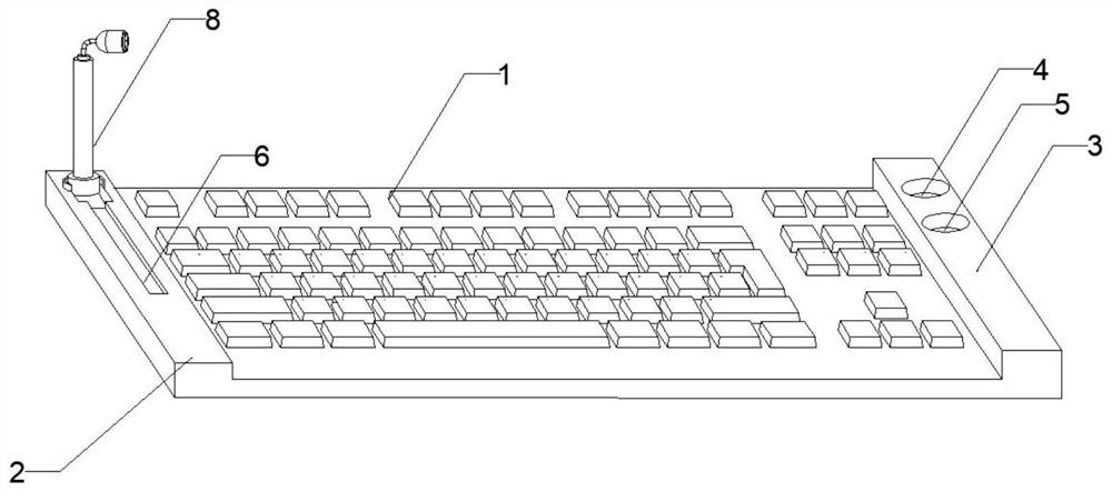
[0029] see figure 1 , the present invention provides a multifunctional dust removal keyboard, the keyboard includes a keyboard main body 1, a multifunctional table 2 is provided on the left side of the keyboard main body, and a storage table 3 is provided on the right side;
[0030] The storage platform 3 is provided with a first storage tank 4 and a second storage tank 5 for storing the fan 24 and the cleaning brush 25 respectively;
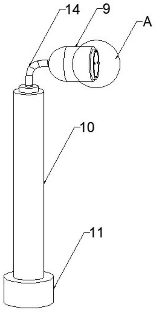
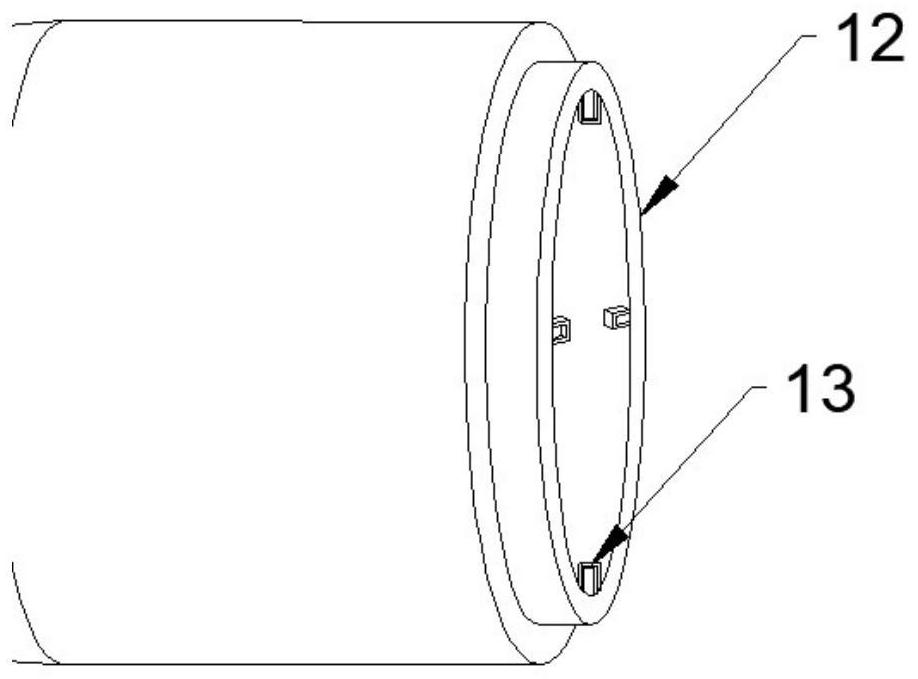
[0031] see figure 2 , image 3 , the multifunctional table 2 is provided with a groove 6, a power cord 7 and a multifunctional machine 8, one end of the power cord 7 is connected to the keyboard main body 1, and the other end is drawn from the groove 6 to be connected to the multifunctional machine 8. The multifunction machine 8 includes a motor 9 , a telescoping rod 10 and a base 11 arranged in sequence from top to bottom. The motor 9 is provided with a connection port 12 for connecting a fan 24 .
[0032] see Figure 4 , based on the abov...
Embodiment 2
[0045] A multifunctional dust-removing keyboard, the keyboard includes a keyboard body 1, a multifunctional table 2 is arranged on the left side of the keyboard body, and a storage table 3 is arranged on the right side;
[0046] The storage platform 3 is provided with a first storage tank 4 and a second storage tank 5 for storing fans and cleaning brushes respectively;
[0047] Described multi-function table 2 is provided with groove 6, power cord 7 and multi-function machine 8, and described power cord 7 one end is connected with keyboard main body 1, and the other end is drawn from groove 6 and is connected with multi-function machine 8, and described multi-function machine The functional machine 8 includes a motor 9 , a telescoping rod 10 and a base 11 arranged sequentially from top to bottom. The motor 9 is provided with a connection port 12 for connecting a cleaning brush 25 .
[0048] see Figure 7 , based on the above embodiment, the inner wall of the connection port 12 ...
PUM
 Abstract
Description
Claims
Application Information
PatSnap Eureka turns technology decisions into work you can execute. Powered by our Innovation Knowledge Graph, it runs expert workflows across engineering, life sciences, materials and intellectual property. Get your review-ready output in minutes.


