Wound cooling device and scald treatment machine
A technology for a cooling device and a wound is applied in the directions of a heating device for treatment, a cooling device for treatment, a contraceptive device, etc. Effect
Inactive Publication Date: 2020-12-22
杜义波
11 Cites 2 Cited by
AI-Extracted Technical Summary
Problems solved by technology
But no matter what kind of burn, the pain it brings is very huge. Compared with other wounds, if the moderate and mild burn can be treated in a timely and effective manner after the burn, you can seek medical treatment in time. Effectively sl...
Method used
[0045] The water bottle inlet clamping device 5, the water bottle water inlet clamping device 5 is arranged on the inside of the installation housing 6 top, to provide more stable clamping for the water bottle that enters the water.
[0046] The above-mentioned collapsible box 2 is a prior art, and will not be repeated here. The cooperation of the telescopic rod 7 and the placement base 1 is a pulling type telescopic rod structure, which is a prior art, and will not be described here. The placement base 1 is connected to the installation shell 6 through a telescopic rod 7, so that its height can be adjusted, which is suitable for different patients with different thicknesses of scalded parts, and, with the collapsible box 2, the whole scald treatment machine can be shrunk together when not in use. Small size and easy to carry. The circulating water pumping device 3 can b...
Abstract
The invention discloses a wound cooling device and a scald treatment machine, belongs to the field of scald treatment, and particularly relates to an instant scald treatment device. The machine comprises a placement base, a circulating water pumping device, a wound cooling device and a water bottle water inlet clamping device; a foldable box is arranged on the right end face of the placement base,two telescopic rods are arranged in the placement base, the two telescopic rods are arranged in a sliding groove located in the placement base, and a mounting shell is arranged at the tops of the twotelescopic rods; the circulating water pumping device is arranged in the foldable box and the placement base and can continuously convey water in the foldable box upwards; the wound cooling device isarranged at the right end of the mounting shell and is used for continuously cooling a scalded part to take away heat after being started; and the water bottle water inlet clamping device is arrangedin the top end of the mounting shell, and is used for providing stable clamping for a water bottle for water inlet. According to the machine, emergency cooling and heat dissipation treatment can be provided when arms, legs and other certain ranges of a person are scalded, the device is convenient to carry, and cooling and heat absorption within an effectively prolonged time can be conducted through a bottle of water under the water shortage condition.
Application Domain
Therapeutic coolingTherapeutic heating
Technology Topic
PhysicsEngineering +2
Image
Examples
- Experimental program(1)
Example Embodiment
[0041]The following are specific embodiments of the present invention in conjunction with the accompanying drawings to further describe the technical solutions of the present invention, but the present invention is not limited to these embodiments.
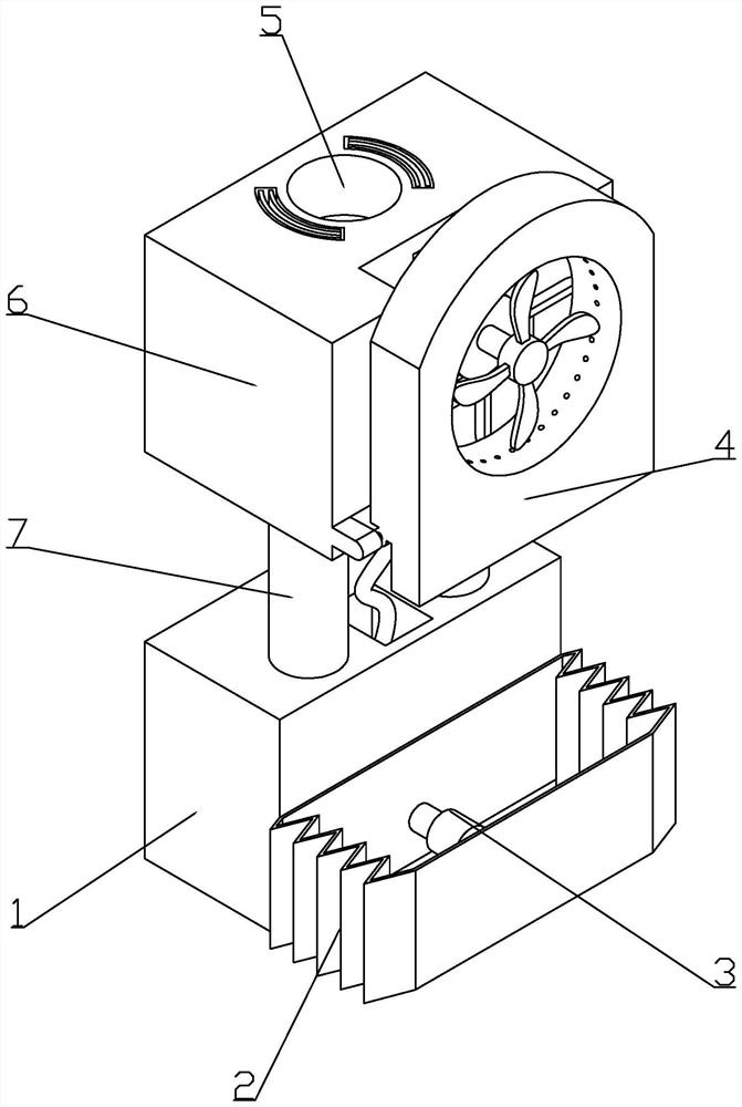
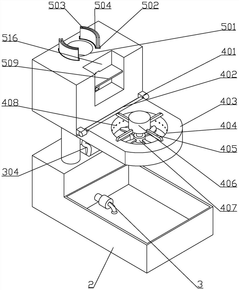
[0042]Such asfigure 1 As shown, a scald treatment machine includes a placement base 1, a foldable box 2 is provided on the right end of the placement base 1, two telescopic rods 7 are provided in the placement base 1, and two telescopic rods 7 are set in the placement base 1. In the sliding groove, the top of the two telescopic rods 7 is provided with a mounting shell 6;
[0043]Circulating water pumping device 3, the circulating water pumping device 3 is arranged inside the base 1 where the foldable box 2 is placed, and can continuously transport the water in the foldable box 2 upwards;
[0044]The wound cooling device 4, which is arranged at the right end of the mounting housing 6, takes away heat for the continuous cooling of the burned area after activation;
[0045]The water bottle water inlet clamping device 5 is arranged inside the top end of the mounting housing 6 to provide a more stable clamping for the water bottle for water inlet.
[0046]The above-mentioned foldable box 2 is a prior art, which will not be repeated here. The cooperation of the telescopic rod 7 and the placement base 1 is a pull-type telescopic rod structure, which is the prior art, and will not be repeated here. The placement base 1 and the mounting shell 6 are connected by a telescopic rod 7, so that the height can be adjusted, which is suitable for different patients with different thicknesses of burned parts. Moreover, with the collapsible box 2, the entire scald treatment machine shrinks together when not in use. Small size and easy to carry. The circulating water pumping device 3 can perform circulating water pumping when the water source is insufficient or in a moving picture, so as to effectively extend the temperature and heat absorption time for the scald wound. The wound cooling device 4 combines water and wind to better dissipate heat for the wound, and has a larger area for cooling, which is suitable for scalds with different scald areas. Water bottle water holding device 5, this device is mainly used when going to the doctor or when the water source is insufficient, when the water bottle needs to be used to fill the scald treatment machine, when the scalded person’s hand is injured or cannot be used at the same time In the case of a hand-held water bottle and a scald treatment machine, the device is used to clamp the water bottle so that the water bottle is fixed on the scald treatment machine to achieve continuous water inflow.
[0047]Such asfigure 2 withFigure 4 As shown, the water bottle inlet holding device 5 includes a water inlet groove 501. The water inlet groove 501 is cylindrical and is arranged in the middle of the top of the mounting housing 6. The lower part of the water inlet groove 501 is provided with an inverted conical water inlet 505 and an inverted conical water inlet 505. The water outlet end is provided with a first connecting pipe 506, the end of the first connecting pipe 506 is provided with a first one-way valve 507, and the output end of the first one-way valve 507 is provided with a second connecting pipe 521. When pouring water into the scald treatment machine, the mouth of the water pouring bottle is aligned with the water inlet groove 501 and inserted. The water can flow from the water inlet groove 501 through the conical water inlet 505 into the first connecting pipe 506, and pass through the first check valve After 507, enter the second connecting pipe 521. The first one-way valve 507 is for one-way conduction from the first connecting pipe 506 to the second connecting pipe 521 to prevent the backflow of water. The inverted conical water inlet 505 is set to make the water flow into the first connecting pipe faster. 506 in.
[0048]Such asFigure 4 versusFigure 8 As shown, the inside of the right end surface of the mounting housing 6 is provided with a first rectangular groove 516, the first rectangular groove 516 is open toward the upper end and the right end, the left end wall of the first rectangular groove 516 is provided with a second sliding groove 508, the second sliding groove 508 is rectangular and penetrates toward the left and right sides. The opening width at the left end is smaller than the opening width at the right end. A pressing plate 509 is slid in the first rectangular groove 516. The end of the pressing plate 509 is slidably arranged inside the second sliding groove 508. A first spring 510 is arranged between the bottom surfaces of the two sliding grooves 508, and the second sliding groove 508 is also provided with a third rectangular groove 566. The third rectangular groove 566 is connected to the second sliding groove 508 and has a width greater than that of the second sliding groove 508. A first push-pull plate 511 is slidably provided in the third rectangular groove 508. The right end of the first push-pull plate 511 extends into the second sliding groove 508 and is fixedly connected to the left end of the pressure plate 509. The upper end of the first push-pull plate 511 is provided with a folding airbag 513. The upper end of the foldable airbag 513 is fixedly connected with the top plate 514 located at the upper end of the third rectangular groove 508. The middle part of the first push-pull plate 511 is provided with a first connecting hose 512 connecting the inside to the outside of the folded airbag 513. Connect the tube 518 horizontally. When the scald treatment machine is not in use, the pressing plate 509 is pressed in the lower position in the first rectangular groove 516, the first spring 510 is compressed, and the pressing plate 509 drives the first push-pull plate 511 to remain in the lower position. The folded airbag 513 fixedly connected to the upper end of the push-pull plate 511 is stretched to the maximum state. The foldable part of the folding airbag 513 has a built-in folding skeleton, so that the folding airbag 513 is folded and opened according to a certain trajectory during the folding process.
[0049]Such asPicture 9 As shown, the end of the transverse connecting pipe 518 is provided with a bifurcation, and the two ends are respectively connected to two third connecting pipes 520 arranged symmetrically about the transverse axis of the water inlet groove 501 inside the mounting housing 6, and the upper end of each third connecting pipe 520 is connected To the arc sealing grooves 502, the arc sealing grooves 502 are symmetrically arranged at both ends of the water inlet groove 501, the arc sealing grooves 502 open toward the upper end, and an arc sliding block 523 is slidably arranged in each arc sealing groove 502. When the folded airbag 513 is stretched to the maximum state by the first push-pull plate 511, the gas inside the two arc-shaped sealing grooves 502 is collected into the transverse connecting pipe 518 through the two third connecting pipes 520, and is finally sucked into the folded airbag 513 At this time, there is no less gas in the arc-shaped sealing groove 502, and the arc-shaped sliding block 523 is adsorbed inside the arc-shaped sealing groove 502. When the scald treatment machine is not in use, the arc-shaped sliding block 523 is stowed so that it is stowed when not in use to avoid affecting the portability of the scald treatment machine. In addition, the retracted arc sliding block 523 also provides force protection to prevent it from being damaged by other objects after being extended when it is not in use.
[0050]Such asPicture 10 As shown, the arc-shaped sliding block 523 is provided with an arc-shaped sliding groove 568, the arc-shaped sliding groove 568 is open toward the upper end, and the top of the arc-shaped sliding groove 568 is provided with an arc-shaped stop block 524. The arc-shaped stop block 524 is connected to On the front and rear walls of the arc sliding groove 568, the arc sliding groove 568 is divided into left and right parts. The arc sliding groove 568 is located on the side of the arc stop block 524 away from the water inlet groove 501 and is provided with a first push plate 504, the arc-shaped sliding groove 568 is located on the side of the arc-shaped stop block 524 close to the water inlet groove 501, and is provided with a second push plate 503. The lower end of the first push plate 504 extends into the arc-shaped sliding groove 568, and the arc There are springs between the bottom front and rear ends of the arc-shaped sliding groove 568. The lower end of the second push plate 503 extends into the arc-shaped sliding groove 568, and there is a spring between the bottom front and rear ends of the arc-shaped sliding groove 568. The inside of the sliding groove 568 is located at the lower end of the second push plate 503 and is provided with a push block 525 with a curved surface at the lower right end. The push block is arranged in the middle part of the curved sliding groove 568, and the length is much smaller than the length of the curved sliding groove 568. A second telescopic rod 531 is fixedly connected to the lower end of the block 525. The second telescopic rod 531 is slidably arranged inside the second telescopic housing 530. The second telescopic housing 530 is arranged on the upper end of the horizontal sliding block 528. The pushing block 525 and the horizontal sliding block 528 There is a second spring 532 surrounding the second telescopic rod 531 and the second telescopic housing 530. The arc-shaped sliding block 523 is located in the middle of the bottom of the arc-shaped sliding groove 568. A transverse sliding groove 529 is provided. The 528 reciprocatingly slides left and right in the horizontal sliding groove 529 to limit the displacement of the horizontal sliding block 528 back and forth. A third spring 527 is arranged between the horizontal sliding block 528 and the right end surface of the curved sliding groove 568. The right side of the curved sliding groove 568 A limit block 533 with a curved upper left end is fixed on the wall at a position slightly higher than the second telescopic shell 530. The limit block 533 moves down to the limit when the pushing block 525 moves downward. After the block 533 is in contact, the pushing block 525 is pushed to the left, and the first push plate 504 and the second push plate 503 have built-in steel sheets and are wrapped with a rubber layer. When the scald treatment machine is to be used, the limit of the pressure plate 509 is released, and the pressure plate 509 rebounds under the action of the first spring 10 to drive the first push-pull plate 511 to rebound, thereby driving the folding airbag 513 to contract, and the gas passes through the first spring 10 The first connecting hose 512 connected in the middle of a push-pull plate 511 enters the transverse connecting pipe 518, and then enters into the two third connecting pipes 520 respectively, and finally enters into the two arc-shaped sealing grooves 502, respectively. 523 pushes up the upper end surface of the mounting housing 6. At this time, align the mouth of the water bottle with the water inlet groove 501 and insert it downward. Between the bottom surfaces of the first push plate 504 and the second push plate 503 to be arc-shaped sliding groove 568, springs are provided at the front and back ends of the arc-shaped sliding groove 568 for resetting use after being pressed by an external force. This embodiment Not shown in the drawings. Take the common mineral water bottle on the market as an example. The lower part of the bottle mouth is a round surface with a gradually increasing diameter. When it is inserted, it first contacts the second push plate 503 closer to the water inlet 501. The second push plate 503 is pushed down in the arc-shaped sliding groove 568 to compress the spring at the lower end of the second push plate 503. The second push plate 503 is pushed down to drive the pushing block 525 at its lower end to move downward together, and the second telescopic rod 531 fixedly connected to the bottom of the driven pushing block 525 moves downward in the second telescopic housing 530, compressing the second The spring 532 continues to push the second push plate 503 down until the pushing block 525 contacts the limiting block 533, and the arc surface of the pushing block 525 contacts the limiting block 533 arc surface. Under the action of the arc surface, The pushing block 525 moves in the direction of the first pushing plate 504, and drives the horizontal sliding block 528 fixedly connected to the second telescopic housing 530 to slide toward the first pushing plate 504 in the horizontal sliding groove 529 to stretch the third spring 527. The first push plate 504 is at a higher position on the slope where the water bottle touches, and it will be above the second push plate 503 in the vertical direction. When the push block 525 is pushed to the left, it will be at the position of the first push plate 504. Below, after the pushing block 525 moves to the left under the pushing action of the second pushing plate 504 to be out of contact, under the action of the second spring 532, the pushing block 525 is pushed upwards, giving the first pushing plate 504 an upward pushing force. At this time, the second push plate 503 has been pushed to the lower end to contact the limit block 533, and the push block 525 can push the first push plate 504 a little bit upward after ensuring that the second push plate 503 has been pushed to the lower end. , Cooperate with the steel sheet in the first push plate 504 and the outer rubber layer to clamp the two sides of the water bottle tighter, and due to the elasticity of the steel sheet, there is a lateral clamping force on both sides of the water bottle when clamping the water bottle , To avoid losing the clamping situation once the water in the water bottle flows out too much and becomes lighter, effectively enhancing the clamping strength and stabilizing the clamping time.
[0051]Such asfigure 2 versusFigure 4-7As shown, the wound cooling device 4 shown includes two hinge joints 401 arranged symmetrically on the bottom right end surface of the mounting housing 6, a hinge shaft 402 is arranged between the two hinge joints 401, and the right side of the hinge shaft 402 is connected with Rotating the housing 403, the hinge shaft 402 is provided with a torsion spring for resetting after rotation. In the initial state of the torsion spring, the rotating housing 403 is opposite to the mounting housing 6 and the right end of the rotating housing 403 is rounded. , The middle of the rotating housing 403 is provided with a first through hole 404, the upper side of the first through hole 404 is provided with four motor support rods 405 connected to the middle, and the middle of the four motor support rods 405 is provided with a drive motor 406, a drive motor 406 The output end is waterproof. The output end of the driving motor 406 extends to the lower end of the first through hole 404. The output end of the driving motor 406 is provided with a rotating head 407. The middle of the rotating head 407 is provided with four fan blades 410 along the circumferential direction. In the initial state, the wound cooling device 4 rests on the right side of the mounting housing 6, and the driving motor 406 presses the pressure plate 509 in the first rectangular groove 516 to a lower position. To use the wound cooling device 4, press the rounded part at the right end of the rotating housing 403 clockwise until the fan blade 410 is directly facing the foldable box 2 below. The arrangement of the torsion spring keeps the wound cooling device 4 in a stowed state when not in use, and can provide a supporting force for pressing the lower end of the driving motor 406 on the pressure plate 509. The four motor support rods 405 clamp the driving motor 406, so as not to block the air inlet of the fan blade 410 while maintaining stable clamping.
[0052]Such asfigure 2 versusFigure 4-7As shown, the upper left end of the rotating shell 403 is provided with a strip-shaped protrusion 464. The length of the strip-shaped protrusion 464 is shorter than the length of the rotating shell 403, and is symmetrical along the center line of the left and right directions of the rotating shell 403. There is an L-shaped water passage 430. The cross-sectional shape of the L-shaped water passage 430 is the same as that of the strip protrusion 464, and the length and width are slightly shorter than the strip protrusion 464. The upper exit of the L-shaped water passage 430 penetrates the strip protrusion 464 upward. , The strip-shaped protrusions 464 are symmetrically provided with second through holes 417 in the left and right side walls of the vertical part of the L-shaped water passage 430, and each second through hole 417 is slidably provided with a third sliding rod 416. One end of the three sliding rods 416 located inside the L-shaped water passage 430 is provided with a vertical plate 420. On the left and right side walls of the strip-shaped protrusions 464, two through holes 417 are symmetrically arranged up and down at a time facing the vertical plate 420. In the spring grooves 418, a fourth spring 419 is provided between each vertical plate 420 and the bottom surfaces of the two nearest spring grooves 418. There is only an L-shaped water passage 430 in the strip protrusion 464, and the cross-sectional shape is the same as that of the strip protrusion 464, so that the L-shaped water passage has a larger receiving space when connecting the water flowing down from the upper part, and the water can flow down smoothly. Will not leak from both sides.
[0053]Such asfigure 2 versusFigure 4-7As shown, the output end of the second connecting pipe 521 is connected with a vertical communicating pipe 411. The cross-sectional shape of the vertical communicating pipe 411 is the same as the shape of the strip protrusion 464, and its length and width are slightly smaller than the length and width of the strip protrusion 464. The lower right end of the body 6 is provided with a convex opening 467, the upper corner of the convex part of the convex opening 467 has an inclination 466 at the right end corner, the lower end of the vertical connecting pipe 411 penetrates to the convex opening 467, the upper end of the convex opening 467 is located at the upper end of the vertical connecting pipe 411 Two fifth half-through grooves 412 are symmetrically arranged on the left and right sides. Each fifth half-through groove 412 opens toward the lower volume and has a length slightly longer than the vertical connecting pipe 411. Each fifth half-through groove 412 is located in a vertical connection. A water baffle 415 is hinged on the side of the lower part of the pipe 411. The length of the water baffle 415 is slightly longer than the length of the vertical connecting pipe 411. The hinged joints of the water baffle 415 and the front and rear side walls of the fifth half-channel 412 are provided with torsion springs. One end of the torsion spring is set on the hinge shaft fixed to the water baffle 415, and the other end is set in the side wall of the fifth half-through groove 412. Each fifth half-through groove 412 is also provided with a sliding limit block 414 for sliding The limit block 414 has protrusions on the side facing the water baffle. When the sliding limit block 414 is not pressed, the protrusions limit the rear end of the water baffle 415 at the hinge joint and prevent the water baffle. 415 is pushed by water, a plurality of fifth springs 413 are arranged between the upper side of each sliding limit block 414 and the fifth half through groove 412, and the left and right side walls of the convex part of the upper end of the convex opening are symmetrically provided with limit holes 421. The size of the limiting hole is adapted to the third sliding rod 416. In the process of rotating and rotating the shell 403 around the two hinge joints 401, before the strip-shaped protrusions 464 have been extended into the upper convex part of the convex opening 467 to a fitted state, the two pieces are attached to the two second pieces respectively. The third sliding rod 416 in the through hole 464 only slightly protrudes from the left and right side walls of the strip-shaped protrusion 464 at the end, and due to the existence of the inclination angle 466, the strip-shaped protrusion 464 will not rotate into the convex opening 467 due to the existence of the inclination angle 466. Due to the influence of the side wall of the convex opening 467, it cannot be aligned and entered. In the process of attaching the strip-shaped protrusion 464 to the upper convex surface of the convex opening 467, the strip-shaped protrusion 464 is located on the upper end surface of the L-shaped water passage 430 in contact with the sliding limit block 414, and the sliding limit block 414 is placed on The fifth half-through groove 412 is pushed upward to compress the plurality of fifth springs 413. At this time, the protrusion of the sliding limit block 414 releases the limit of the water baffle 415. At this time, the original water flow flows from the second connecting pipe 521 into the vertical connecting pipe 411, and is blocked by the two baffle plates 415 and cannot flow out. After the limit of the baffle plate 415 is released, the gravity and driving force of the water flow Push the two water baffles 415 to rotate and open, and the water baffles 415 extend into the L-shaped water passage 430 in the strip protrusion 464, and respectively contact the vertical plates 420 on both sides, and continue to wash down in the subsequent water flow. , The water baffle 415 is pushed to rotate, the two water baffles 415 respectively push the vertical plate 420 to the two side walls of the L-shaped water passage 430, and the vertical plate 420 pushes the third sliding rod 416 in the second through hole 464 slides out from inside to outside, compressing the two fourth springs 419, and the third sliding rod extends outward to and extends into the limiting holes 421 at the two ends respectively. After that, as long as the water in the vertical connecting pipe 411 continues to flow down, the The protrusion 464 can be fixed at the convex opening by two third sliding rods 416 under the thrust of the water flow. The lower end of the vertical connecting pipe 411 is provided with a laminating rubber. The water baffle 415 is slightly longer than the vertical connecting pipe 411, so that it can be matched with the laminating rubber at the nozzle when the nozzle is blocked, which is more effective Prevent water leakage. The water baffle 414 not only plays the role of retaining water at the beginning, but also converts the driving force of the water flow into the driving force of the third sliding rod 416, so that it completes the limit of the rotating housing 403, so that it can only rotate in the lower part. When the strip-shaped protrusion 464 at the lower part of the housing 403 is attached to the convex opening 467, and the water in the vertical connecting pipe 411 can smoothly flow into the inside of the L-shaped water passage 430, it can be stably restricted without rebounding It avoids that the water outlets of the ordinary connecting mechanism are not aligned and clamped properly, resulting in water leakage during subsequent water transportation.
[0054]Such asfigure 2 versusFigure 4-7As shown, the output end of the L-shaped water passage 430 is connected to an annular water passage 409. The annular water passage 409 is arranged inside the rotating housing 403 and is arranged around the first through hole 404. The inside of the first through hole 404 is slightly higher than the rotating head 407. A plurality of water outlet holes 408 are provided at the position along the circumferential direction, and the water outlet holes are connected to the annular water passage 409. The water in the L-shaped water passage 430 flows into the annular water passage 409, and then flows out from the water outlet, and falls from a position higher than the rotating head 407 to the top of the fan blade 410. At this time, the drive motor 406 is turned on, and the drive motor 406 outputs The end rotation drives the rotating head 407 to rotate, thereby driving the four fan blades 410 to rotate to break the water droplets encountered and blow them downward along with the wind. Dispose of the burns of the hands or legs underneath, and the lower part of the foldable box 2 can be used to continuously cool the burns and take away the heat. By adjusting the rotation speed of the driving motor 406 and the height of the mounting housing 6, the area and speed of the wind with water can be adjusted to adapt to wounds of different areas and people with different hand and leg thickness.
[0055]Such asFigure 4 As shown, the circulating water pumping device 3 includes a micro water pump 301. The input end of the micro water pump 301 is connected with a water suction pipe 302. The suction port of the water suction pipe 302 is set toward the bottom surface of the foldable box 2, and the bottom shell 1 is provided with a water suction channel 303 to absorb water. The right end of the channel 303 extends out of the bottom casing 1 and is connected to the output end of the micro water pump 301. The left end of the suction channel 303 penetrates upwards. The middle of the top of the bottom casing 1 is provided with a hose placement groove 3041. The mounting casing 6 is located in the second connecting pipe 521. The lower part is provided with a connecting pipe 305, the upper end of the connecting pipe is connected to the second connecting pipe 521, the top of the connecting pipe 305 is provided with a second one-way valve 311, and the second connecting hose 304 is provided between the bottom of the connecting pipe 305 and the suction channel 303. In the initial stage, the second connecting hose 304 can be stored in the hose placement groove 3041. In the case of insufficient water supply, open the foldable box 2 and blow water from the upper part onto the skin of the burned area. The skin on the wound of the vertical person flows down into the collapsible box 2. At this time, the micro water pump 301 is started, the water at the bottom is pumped into the suction pipe 302, and then from the output end of the micro water pump 301 to the suction channel 303 Then, it flows upward from the water suction channel 303 into the second connecting hose 304 to the connecting pipe 305, and after passing through the second one-way valve 311, it merges into the second connecting pipe 521, and merges with the water flowing down from the water bottle for cooling use. . Although water will gradually lose during this process, this action can effectively extend the time of water recycling, and it can heat the burned area for a longer time under the condition of water shortage, and provide more continuous protection and relief for the injured to seek medical treatment. pain.
[0056]The above are only the embodiments of the present invention, and do not limit the scope of patent protection of the present invention. Any equivalent structure or equivalent process transformation made by the content of the description and drawings of the present invention, or directly or indirectly applied to other related The technical field is similarly included in the scope of patent protection of the present invention.
PUM


Description & Claims & Application Information
We can also present the details of the Description, Claims and Application information to help users get a comprehensive understanding of the technical details of the patent, such as background art, summary of invention, brief description of drawings, description of embodiments, and other original content. On the other hand, users can also determine the specific scope of protection of the technology through the list of claims; as well as understand the changes in the life cycle of the technology with the presentation of the patent timeline. Login to view more.
Similar technology patents
Compact range feed source suitable for indoor ultra-broadband wireless communication frequency band
Owner:BEIHANG UNIV
Classification and recommendation of technical efficacy words
- easy to carry
- reduce volume
Method for preparing light fracturing propping agent for multi-hole oil and gas well
Owner:SINOSTEEL LUOYANG INST OF REFRACTORIES RES
Bluetooth communication bracelet
Owner:1MORE ACOUSTIC TECH CO LTD
Display device and electronic product
Owner:GUANGZHOU GOVISIONOX TECH CO LTD
Photography measurement method of scene of a traffic accident
Owner:SHANGHAI JIAO TONG UNIV
Device and method for checking SF6 gas leakage monitoring and alarming apparatuses
Owner:GUANGXI POWER GRID ELECTRIC POWER RES INST
Implant release mechanism
Owner:COOK MEDICAL TECH LLC
Speed reduction box for turbine fracturing
Owner:YANTAI JEREH PETROLEUM EQUIP & TECH
Miniature and Multi-Band RF Coil Design
Owner:HONG KONG APPLIED SCI & TECH RES INST
Automatic washing and dewatering combined device of rotary type mop
Owner:上海祥美网络科技有限公司 +1
Optical imaging system
Owner:SAMSUNG ELECTRONICS CO LTD