Special clamp suitable for L-shaped valve body machining and machining method

A special fixture and valve body technology, applied in the field of hydraulic parts processing, can solve the problem of frequent replacement of fixtures, and achieve the effect of shortening processing time, small size and accurate positioning

Active Publication Date: 2020-12-22
HANDAN HENGGONG METALLURGICAL MACHINERY CO LTD
View PDF9 Cites 0 Cited by
  • Summary
  • Abstract
  • Description
  • Claims
  • Application Information

AI Technical Summary

Problems solved by technology

[0003] This application provides a special fixture and processing method suitable for L-shaped valve body processing to solve the problem that the existing L-shaped valve body requires frequent replacement of fixtures

Method used


Image

  • Special clamp suitable for L-shaped valve body machining and machining method
  • Special clamp suitable for L-shaped valve body machining and machining method
  • Special clamp suitable for L-shaped valve body machining and machining method

Examples


Embodiment 1

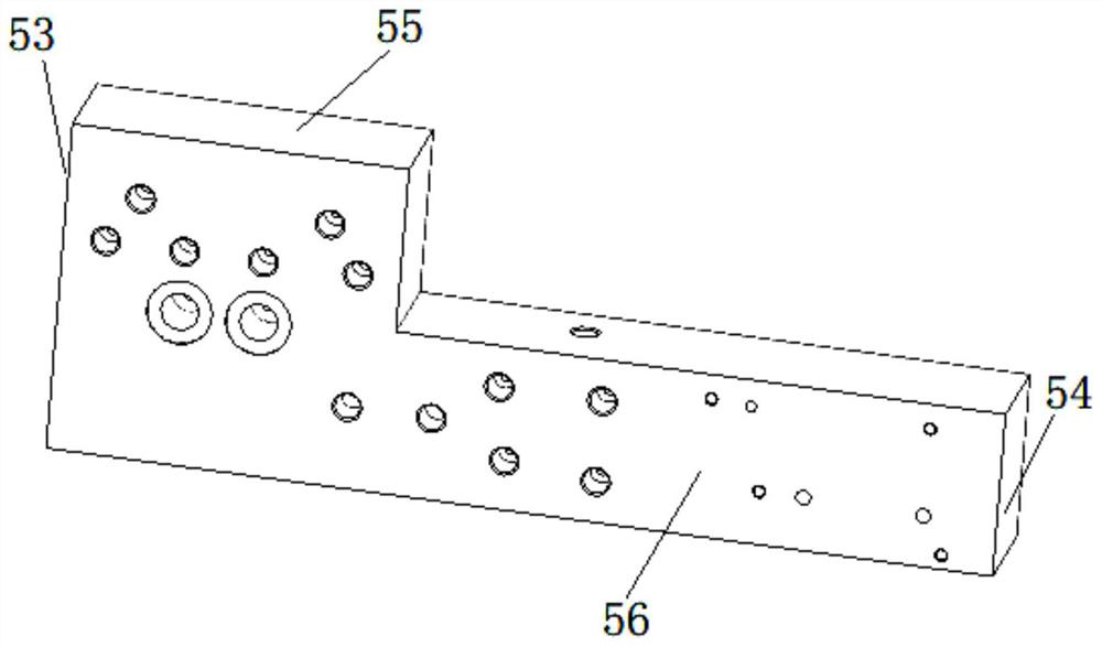
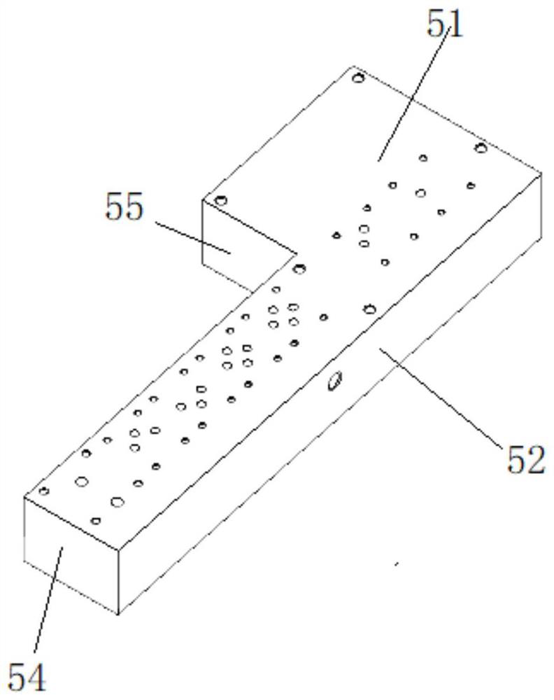
[0051] Embodiment 1: see Figure 1-11 , a special fixture suitable for L-shaped valve body processing. The fixture is used in a crane and can clamp two L-shaped valve bodies 5 at the same time. The L-shaped valve body 5 is provided with a second back 51 and a second front 56 opposite to each other. , the second top surface 55 , the second left side 53 , the second bottom surface 52 , and the second right side 54 connected end to end.

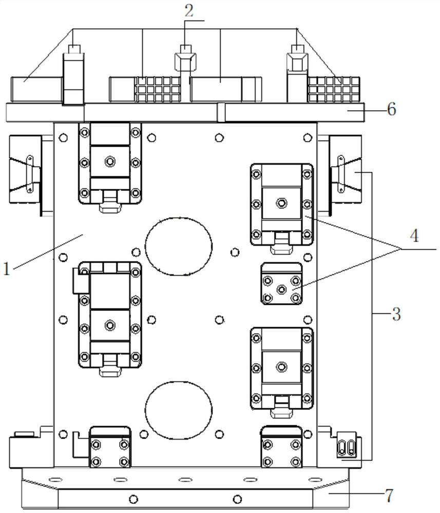
[0052]The special fixture suitable for L-shaped valve body processing includes a main body 1 , a set of first clamping assemblies 2 , two sets of second clamping assemblies 3 and a set of third clamping assemblies 4 . The first clamping assembly 2 includes a pressing plate 21 and a first positioning block 22 . The second clamping assembly 3 includes a first adjustment seat 31 and a second positioning block 32 . The third clamping assembly 4 includes a second adjustment seat 42 and a third positioning block 41 .

[0053] The main body 1 is int...

Embodiment 2

[0062] Embodiment 2, a processing method suitable for the L-shaped valve body 5, the fixture in this embodiment can be divided into three processes during processing to process the L-shaped valve body 5 in all directions, and the processing of the L-shaped valve body 5 Methods include:

[0063] Step 1: Place two L-shaped valve bodies 5 horizontally on the first clamping assembly 2, the second back surfaces 51 of the two L-shaped valve bodies 5 are positioned by the first pressure plate 211 and the two lever-type pressure plates 212, L The second left side 53 and the second bottom surface 52 of the L-shaped valve body are positioned by three first positioning blocks 22, and the second top surface 55 of the L-shaped valve body 5 can be processed after the positioning is completed;

[0064] Step 2: Place the L-shaped valve body 5 processed in Step 1 on two sets of second clamping assemblies 3 , and the second clamping assemblies 3 position the L-shaped valve body 5 on the two fir...


PUM


Abstract

The invention discloses a special clamp suitable for L-shaped valve body machining and a machining method. The special clamp comprises a main body, and a first clamping assembly, a second clamping assembly and a third clamping assembly are arranged on the main body; the first clamping assembly positions the second back face, the second bottom face and the second left side face of an L-shaped valvebody; the second clamping assembly positions the second left side face and the second right side face of the L-shaped valve body; and the third clamping assembly positions the second top face and thesecond bottom face. According to the clamp, the problem that a clamp needs to be frequently replaced when the L-shaped valve body is machined is solved.

Description

technical field [0001] The invention relates to the technical field of hydraulic parts processing, in particular to a special fixture and a processing method suitable for processing an L-shaped valve body. Background technique [0002] The L-shaped valve body used on the crane must ensure its accuracy during the production and processing process. Therefore, when processing the datum surface of the L-shaped valve body, the L-shaped valve body must be positioned. There are three processes in the processing of the L-shaped valve body. Different fixtures are used in different processes. Frequent replacement of fixtures is required in production, which increases costs. Contents of the invention [0003] The present application provides a special fixture and processing method suitable for L-shaped valve body processing, so as to solve the problem that the existing L-shaped valve body requires frequent replacement of fixtures. [0004] A special fixture suitable for processing a...

Claims


Application Information

Patent Timeline
Patent Type & Authority Applications(China)
IPC IPC(8): B23Q3/00
CPCB23Q3/00B23Q2703/10
Inventor 魏志勇高运强魏东华林敏
Owner HANDAN HENGGONG METALLURGICAL MACHINERY CO LTD
Why Eureka
Try Eureka