Rapid maintenance and replacement system for fan of electrical cabinet

A technology for maintenance and replacement of cabinet fans, applied to mechanical equipment, machines/engines, liquid fuel engines, etc., which can solve problems such as inconvenient maintenance and replacement, heavy fans, and fan burdens

Pending Publication Date: 2020-12-22
江苏联峰实业有限公司
View PDF0 Cites 0 Cited by
  • Summary
  • Abstract
  • Description
  • Claims
  • Application Information

AI Technical Summary

Problems solved by technology

[0002] In the production workshop of iron and steel enterprises, the electrical cabinet is usually in continuous work for a long time, such as the rectifier cabinet installed in the steel rolling workshop, which needs to work continuously for 24 hours; this high-intensity continuous operation is used for cooling in the electrical cabinet The fan for cooling causes a great burden, which makes the fan prone to failure; the fan for the electrical cabinet of the iron and steel enterprise is relatively heavy and placed at the bottom of the electrical cabinet, which not only causes inconvenience to maintenance and replacement, but also causes long-term power-off maintenance. Great loss to the production of the enterprise

Method used


Image

  • Rapid maintenance and replacement system for fan of electrical cabinet
  • Rapid maintenance and replacement system for fan of electrical cabinet
  • Rapid maintenance and replacement system for fan of electrical cabinet

Examples


Embodiment Construction

[0048] Embodiments of the present invention are described in detail below, and examples of the illustrated embodiments are illustrated in the drawings, wherein like or similar reference numerals designate the same or similar elements or elements having the same or similar functions throughout. The embodiments described below by referring to the figures are exemplary and are intended to explain the present invention and should not be construed as limiting the present invention.

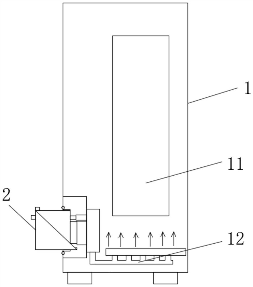
[0049] The rapid maintenance and replacement system for electric cabinet fans of the present invention includes a cabinet body 1, a fan 2 and a maintenance vehicle 3.

[0050] Such as figure 1 In the electrical cabinet shown, the fan 2 is plugged in at the fan interface at the side bottom of the cabinet 1 , and the cabinet 1 is provided with an electrical component 11 and an air duct 12 .

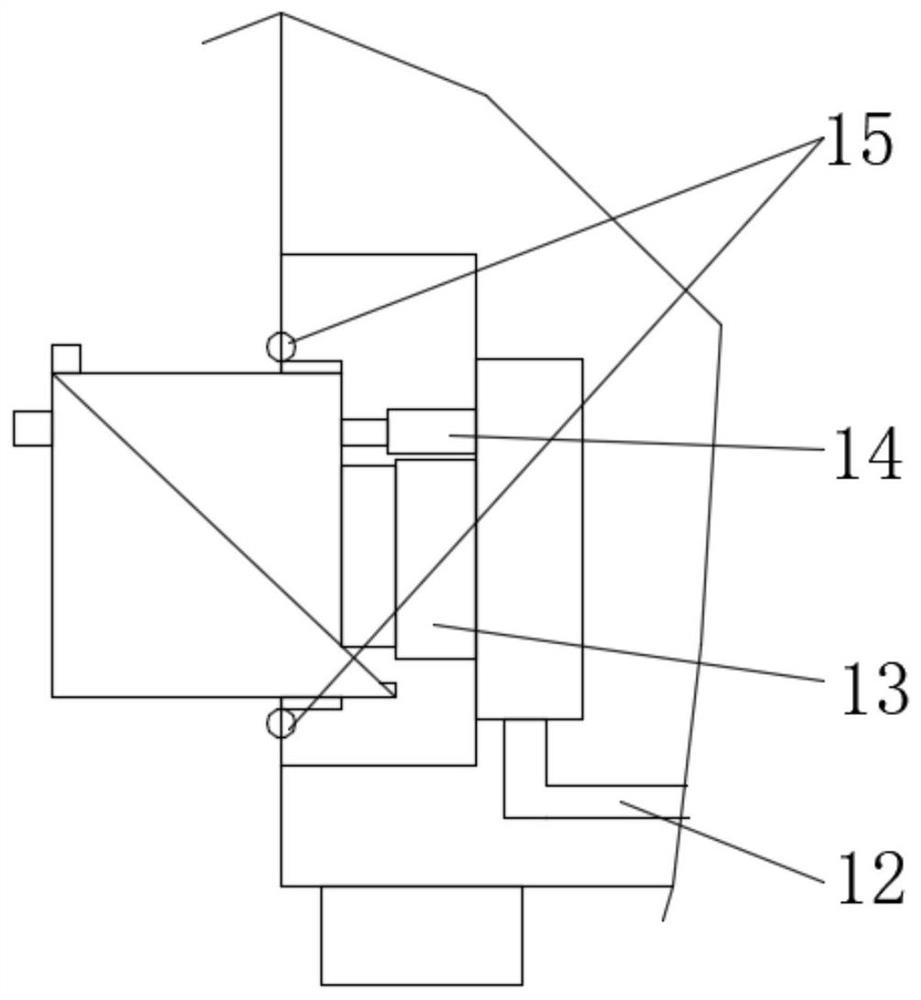
[0051] Such as figure 2 As shown, the joint between the cabinet body 1 and the fan 2 is provided with an air i...


PUM


Abstract

The invention provides a rapid maintenance and replacement system for a fan of an electrical cabinet, and belongs to the field of electrical cabinet matching maintenance. The rapid maintenance and replacement system involves a cabinet body, the fan and a maintenance vehicle; the fan is provided with connector racks, the cabinet body is provided with connector gears, and the fan is inserted and externally hung on the side surface of the cabinet body through the matching between the racks and the gears; an air channel is arranged inside the cabinet body, and airflow is guided into the cabinet body through the air channel for heat dissipation; the maintenance vehicle comprises a handrail and a vehicle plate, vertical rods are arranged on the vehicle plate, a supporting frame is slidably connected to the vertical rods, and maintenance vehicle racks matched with the connector gears are arranged at the front end of the maintenance vehicle; and when the fan of the electrical cabinet is maintained and replaced, a new fan is placed on the supporting frame, the maintenance vehicle is aligned with a fan connector of the cabinet body and pushed forwards, the maintenance vehicle racks act on the connector gears, the connector gears rotate to reversely push the old fan out of the cabinet body, the new fan descends and pushes the old fan away from the cabinet body, then the maintenance vehicle is pulled backwards, and the new fan is inserted into the cabinet body under the driving of the connector gears. The rapid maintenance and replacement system for the fan of the electrical cabinet can achieve rapid maintenance and replacement of the fan.

Description

technical field [0001] The invention belongs to the field of supporting maintenance of electric cabinets, and in particular relates to a quick maintenance and replacement system for fans of electric cabinets. Background technique [0002] In the production workshop of iron and steel enterprises, the electrical cabinet is usually in continuous work for a long time, such as the rectifier cabinet installed in the steel rolling workshop, which needs to work continuously for 24 hours; this high-intensity continuous operation is used for cooling in the electrical cabinet The fan for cooling causes a great burden, which makes the fan prone to failure; the fan for the electrical cabinet of the iron and steel enterprise is relatively heavy and placed at the bottom of the electrical cabinet, which not only causes inconvenience to maintenance and replacement, but also causes long-term power-off maintenance. It will cause great loss to the production of the enterprise. Therefore need t...

Claims


Application Information

Patent Timeline
Patent Type & Authority Applications(China)
IPC IPC(8): B25B27/00F04D29/60
CPCB25B27/00F04D29/601
Inventor 周孝风郑兵前冯建峰丁燕新
Owner 江苏联峰实业有限公司
Why Eureka
Try Eureka