
Lower discharging device of powder and particle material transport vehicle

A technology of a discharging device and a transport vehicle, which is applied in the direction of object transport vehicles, transportation and packaging, and transporting objects, and can solve the problem of dead angles between the discharge port and flange parts, excessive volume of the discharge port, and insufficiently simple structure, etc. problem, to achieve the effect of no dead angle, small size and simple structure

Pending Publication Date: 2020-12-22
张法英
View PDF0 Cites 2 Cited by
  • Summary
  • Abstract
  • Description
  • Claims
  • Application Information

AI Technical Summary

Problems solved by technology

Compared with the upper discharge method, the bottom discharge method has the advantages of simple structure, short required discharge pipe length, relatively smooth discharge, etc., but the bottom discharge structure of the prior art also has certain disadvantages: the bottom Not only is the size of the material port too large, but also the discharge port and the flange have a discharge dead angle, which leads to material retention and unsmooth discharge. At the same time, when the tank is filled with materials, the material will settle and accumulate at the discharge port, which cannot be achieved without a booster. Therefore, the lower discharge structure of the existing structure is usually equipped with more than two boosters, which is heavy, and the structure is not simple enough, inconvenient to use, and labor-intensive.

Method used


Image

  • Lower discharging device of powder and particle material transport vehicle
  • Lower discharging device of powder and particle material transport vehicle
  • Lower discharging device of powder and particle material transport vehicle

Examples


Embodiment 1

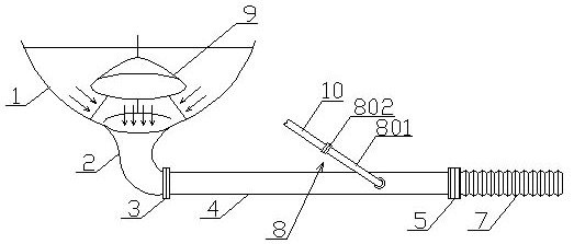
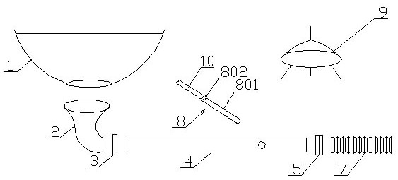
[0025] as attached figure 1 , 2 , 5, a discharge device under a powder material transport vehicle of the present invention, its structure includes a variable diameter elbow 2 arranged on the tank body 1, the variable diameter elbow 2 is arc-shaped, and one port diameter is relatively The diameter of the other port is relatively large, the large diameter end communicates with the bottom of the tank body 1, the small diameter end communicates with the feed end of the connection material pipe 4 through the flange 3, and the discharge end of the connection material pipe 4 passes through The discharge butterfly valve 5 is connected with the discharge hose 7, the connecting material pipe 4 is a straight material pipe, and a material booster 8 is arranged on the connecting material tube 4, and the material booster 8 includes a A booster pipe 801 connected to each other, and a booster valve 802 connected to the external air source 10 is arranged on the booster tube 801 .

[0026] A ...

Embodiment 2

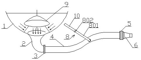
[0028] as attached image 3 , 4 As shown, a discharge device under a powder material transport vehicle of the present invention has a structure including a reducing elbow 2 arranged on the tank body 1, the reducing elbow 2 is arc-shaped, and the diameter of one port is relatively small , the diameter of the other port is relatively large, the large-diameter end communicates with the bottom of the tank body 1, the small-diameter end communicates with the feed end of the connection material pipe 4 through the flange 3, and the discharge end of the connection material pipe 4 passes through the discharge The butterfly valve 5 is connected with the quick connector 6, the connecting material pipe 4 is an S-shaped material pipe, and a material boosting device 8 is arranged on the connecting material tube 4, and the material boosting device 8 includes an auxiliary material connected with the connecting material tube 4. The push tube 801 is provided with a boost valve 802 connected wi...


PUM


Abstract

The invention provides a lower discharging device of a powder and particle material transport vehicle and belongs to the technical field of manufacturing of powder and particle material transport vehicles. The lower discharging device structurally comprises a reducing elbow arranged on a tank body; the reducing elbow is arc-shaped; the diameter of one end of the reducing elbow is relatively small;the diameter of the other end of the reducing elbow is relatively large; the large-diameter of the reducing elbow communicates with the bottom of the tank body; the small-diameter end of the reducingelbow communicates with the feeding end of a connecting material pipe through a flange; the discharging end of the connecting material pipe is connected with a quick coupling or a discharging hose through a discharging butterfly valve; a material boosting device is arranged on the connecting material pipe; and a gas collection dustproof device is arranged right above the joint of the reducing elbow and the tank body in the tank body. The lower discharging device has the advantages of reasonable design, simple structure, small size, smooth discharging, convenience in use and the like.

Description

technical field [0001] The invention relates to a powder material transport vehicle, in particular to a bottom discharge device of the powder material transport vehicle. Background technique [0002] There are usually two ways of unloading powder material transport vehicles, namely upper discharge and lower discharge. Compared with the upper discharge method, the bottom discharge method has the advantages of simple structure, short required discharge pipe length, relatively smooth discharge, etc., but the bottom discharge structure of the prior art also has certain disadvantages: the bottom Not only is the size of the material port too large, but also the discharge port and the flange have a discharge dead angle, which leads to material retention and unsmooth discharge. At the same time, when the tank is filled with materials, the material will settle and accumulate at the discharge port, which cannot be achieved without a booster. work, so the lower discharge structure of ...

Claims


Application Information

Patent Timeline
Patent Type & Authority Applications(China)
IPC IPC(8): B60P3/22B60P1/60
CPCB60P3/2245B60P1/60
Inventor 张法英
Owner 张法英
Learn More