Placing frame convenient to take for cable machining

A technology for placing racks and cables, applied in the field of placing racks for cable processing, can solve the problems of a large amount of cable discharge, the inability to take out manual removal, and the inability of workers to recover in time.

Inactive Publication Date: 2020-12-22
湖南新耒传导材料科技有限公司
View PDF1 Cites 0 Cited by
  • Summary
  • Abstract
  • Description
  • Claims
  • Application Information

AI Technical Summary

Problems solved by technology

The above-mentioned patents have the following disadvantages: the cable removal process needs to be taken out and cut manually according to the length, and the above-mentioned device cannot take into account the function of manual removal, that is, when the cable is taken out, the motor is still rotating. Too fast leads to excessive cable discharge, and workers cannot recover in time, which leads to cable entanglement accidents

Method used


Image

  • Placing frame convenient to take for cable machining
  • Placing frame convenient to take for cable machining
  • Placing frame convenient to take for cable machining

Examples


Embodiment 1

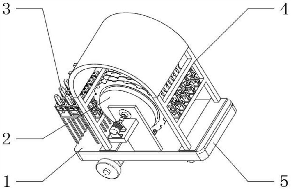
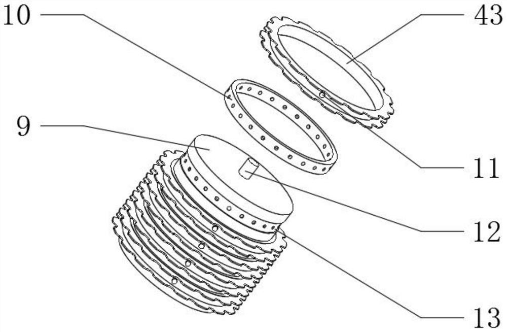
[0036] An easy-to-take display rack for cable processing, such as Figure 1-8As shown, it includes a bottom plate 1, the top outer wall of the bottom plate 1 is fixedly connected with a bracket 7, the inner wall of the bracket 7 is connected with a storage assembly 2 through bearing rotation, and the top outer wall of the bottom plate 1 is fixedly connected with a discharge assembly 3, a sorting assembly 4 and a stuck Assembly 6; the storage assembly 2 includes a main cylinder 9 and a trunnion 12, the number of the trunnions 12 is two, the trunnion 12 is rotatably connected to the inner wall at both ends of the main cylinder 9, and the outer wall of the main cylinder 9 is provided with a chute 13, and the sliding The inner wall of the slot 13 is rotatably connected with a collar 10, the inner wall of the collar 10 and the chute 13 are provided with pin holes, the outer wall of the collar 10 is fixedly connected with the cable box 43, the outer walls of both sides of the box 43 ...

Embodiment 2

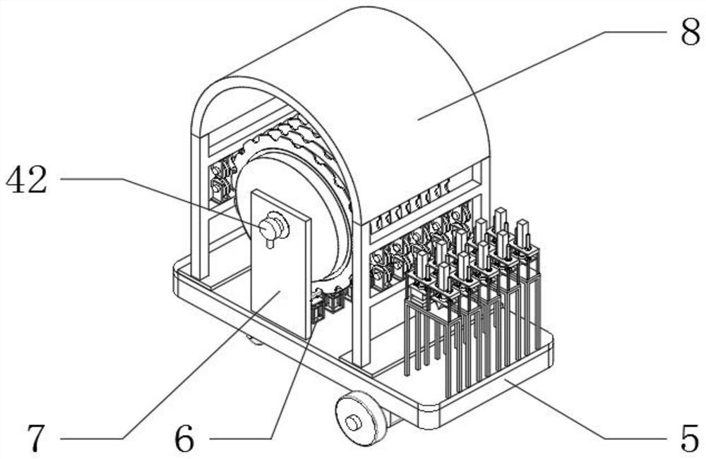
[0043] An easy-to-take display rack for cable processing, such as figure 1 , 7 As shown, for the operation of the main shaft 14; this embodiment makes the following improvements on the basis of embodiment 1: the outer wall of one side of the bracket 7 is welded with a mounting plate 31, and the outer wall of the top of the mounting plate 31 is fixedly connected with a bracket. The middle inner wall is rotatably connected with a rotary shaft through a bearing, the outer wall at one end of the rotary shaft is fixedly connected with a handwheel, and the outer wall at the other end of the rotary shaft is connected to the outer wall at one end of the trunnion 12 through a coupling.

[0044] In this embodiment, when the device is started and needs to be moved, the drive box 5 receives an external remote control instruction, and the control device moves to a designated position. When the cable enters the device, the personnel will send the cable through the arrangement assembly 4, an...


PUM


Abstract

The invention discloses a placing rack convenient to take for cable machining and relates to the technical field of cable machining equipment. The placing frame aims at solving the problem about taking two functions of automatic feeding and manual material taking into consideration. The placing frame specifically comprises a bottom plate. The outer wall of the top of the bottom plate is fixedly connected with a support, and the inner wall of the support is rotationally connected with a storage assembly through a bearing. The outer wall of the top of the bottom plate is fixedly connected with adischarging assembly, a splitting assembly and a clamping assembly. The storage assembly comprises a main cylinder and two trunnions which are rotationally connected to the inner walls of the two ends of the main cylinder. Sliding grooves are formed in the outer wall of the main cylinder, and lantern rings are rotationally connected to the inner walls of the sliding grooves. According to the placing frame convenient to take for cable machining, through the arrangement of the storage assembly, when a first air cylinder contracts, a connecting rod is disengaged from the inner wall of a pin hole, the lantern rings are in a movable state relative to the main cylinder, automatic rotation can be achieved through manpower, field workers can conveniently draw and pull cables according to the needed length, meanwhile, the number of wire boxes and the number of the lantern rings are both five, and storage of various cables of different specifications can be met.

Description

technical field [0001] The invention relates to the technical field of cable processing equipment, in particular to an easy-to-take display rack for cable processing. Background technique [0002] After the cable processing is completed, it needs to be placed on a certain temporary storage device for standby. However, the existing placement device has a relatively simple structure and cannot satisfy the compatibility of the two functions of automatic winding and manual picking. [0003] After retrieval, the Chinese patent application number is 201920969867.6 , which discloses a wire and cable placement rack, including: a support chassis, which is a box structure without a cover; a wire and cable support mechanism, which supports the rotation of the wire and cable The wire and cable support mechanism at least includes two sets of rolling support units with the same structure, which are arranged symmetrically on both sides inside the support chassis; the rolling drive mechanis...

Claims


Application Information

Patent Timeline
Patent Type & Authority Applications(China)
IPC IPC(8): B65H75/02
CPCB65H75/02
Inventor 赵峥孙爱国曾智俊曾小云汤小金
Owner 湖南新耒传导材料科技有限公司
Why Eureka
Try Eureka