
Degassing tank and control method for performing water circulation exhaust by using degassing tank

A technology of degassing tank and water inlet pipe, applied in the direction of degassed water/sewage treatment, etc., can solve the problems of difficult gas precipitation, affecting the heat transfer efficiency of the cooling system, poor gas-water separation effect, etc.

Pending Publication Date: 2020-12-22
中科智寰(北京)科技有限公司
View PDF0 Cites 0 Cited by
  • Summary
  • Abstract
  • Description
  • Claims
  • Application Information

AI Technical Summary

Problems solved by technology

[0005] In view of this, one of the objectives of the present invention is to provide a degassing tank to solve the problem that the gas-liquid separation device in the prior art cannot well solve the impact of water entering the liquid in the water tank, and new air bubbles are generated during the impact process At the same time, due to the violent movement and instability of the water in the water tank, it is difficult to precipitate gas. As a result, the gas-water separation effect is poor, which affects the technical problem of the heat transfer efficiency of the entire cooling system

Method used


Image

  • Degassing tank and control method for performing water circulation exhaust by using degassing tank
  • Degassing tank and control method for performing water circulation exhaust by using degassing tank

Examples


Embodiment Construction

[0034] In order to make the purpose, technical solution and advantages of the present invention clearer, the technical solution of the present invention will be described in detail below. Apparently, the described embodiments are only some of the embodiments of the present invention, but not all of them. Based on the embodiments of the present invention, all other implementations obtained by persons of ordinary skill in the art without making creative efforts fall within the protection scope of the present invention.

[0035] As mentioned in the background technology, the existing gas-liquid separation device, that is, the degassing tank, mainly relies on the buffering effect of the water tank. Because the gas density is lower than the liquid density, the bubbles float up and precipitate gas, but it cannot solve the problem of water entering the water tank. The impact of the liquid will generate new bubbles during the impact process. In addition, due to the violent movement of...


PUM


Abstract

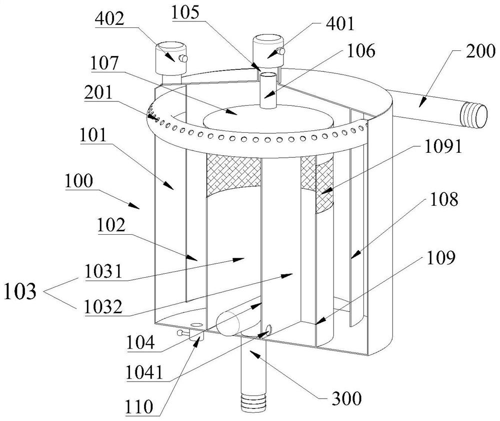
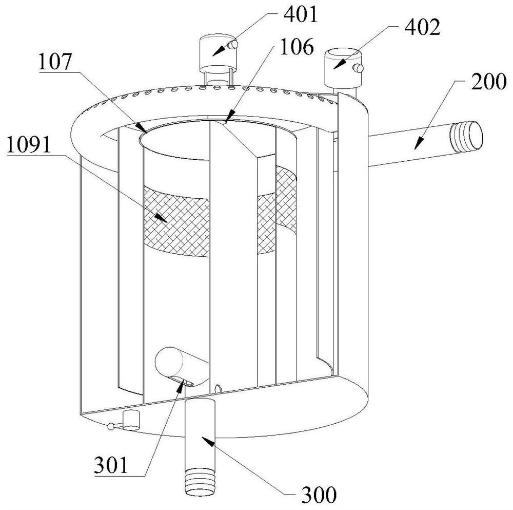
The invention provides a degassing tank and a control method for water circulation exhaust through the degassing tank, and relates to the technical field of gas-liquid separation devices. A degassingtank body is arranged to be a tank body with a cavity body, the cavity body is sequentially provided with an outer cavity, a middle cavity and an inner cavity from the inner wall to the interior, andthe bottom of the outer cavity communicates with the bottom of the middle cavity; the top of the middle cavity communicates with the top of the inner cavity; a water inlet pipe is arranged at the upper part of the degassing tank body and communicates with the outer cavity; a water outlet pipe is arranged at the lower part of the degassing tank body and communicates with the inner cavity; and an exhaust valve is arranged at the upper part of the degassing tank body and communicates with the cavity body. The invention also provides a control method for performing water circulation exhaust by using the degassing tank. The degassing tank is used for reducing the impact of water flow on the degassing tank and preventing new bubbles from being generated, and due to circuitous advancing of the water flow, water in the degassing tank can be prevented from violently moving and stably advance, so that more gas is separated out, the separation effect of gas-water separation is improved, and the purpose of improving the heat exchange efficiency of a water cooling system is achieved.

Description

technical field [0001] The invention relates to the technical field of gas-liquid separation devices, in particular to a degassing tank and a control method for water circulation exhaust by using the degassing tank. Background technique [0002] Most high-power heating systems use liquid cooling to dissipate heat. In liquid cooling systems, the heat transfer medium is liquid. If there is gas in the liquid, it usually exists in the pipeline in the form of bubbles, which will greatly reduce the exchange rate of liquid cooling. Thermal efficiency, so generally in the liquid cooling heat dissipation circulation system, the gas-liquid separation device will be used. [0003] The liquid-cooled heat dissipation system is powered by a special water pump. Usually, the water-cooled circulation system is divided into an open circulation system and a closed circulation system. The characteristics of the open circulation system are that it has a high-level water tank, and there is an ai...

Claims


Application Information

Patent Timeline
Patent Type & Authority Applications(China)
IPC IPC(8): C02F1/20
CPCC02F1/20
Inventor 寇斐汪健宇马永健
Owner 中科智寰(北京)科技有限公司
Learn More