Conveying and flattening device based on clothing fabric dyeing

A cloth and clothing technology, applied in the field of conveying and flattening devices, can solve the problems of difficulty in ensuring the drying of the cloth, insufficient dyeing of the cloth, and low flatness

Inactive Publication Date: 2020-12-22
广州玉诚电子贸易有限公司
View PDF0 Cites 0 Cited by
  • Summary
  • Abstract
  • Description
  • Claims
  • Application Information

AI Technical Summary

Problems solved by technology

[0002] With the improvement of living standards, people's requirements for clothing are getting higher and higher. There are various types of clothing on the market, and people have more and more choices. Therefore, the processing of clothing is becoming more and more strict. However, Clothing will go through the dyeing process during the processing process. Before dyeing, the fabric needs to be flattened and then transported to the dyeing pool. However, the effect of the existing flattening roller is not obvious, and the partially wrinkled fabric is flattened by the roller It will also return to its wrinkled state later, making the fabric insufficiently dyed
[0003] The main reason for the insufficient dyeing of the cloth is that the folded cloth returns to its original folds after being flattened by the rotating shaft, and the flatness of the cloth surface is too low, which causes the cloth to overlap and stick together during the dyeing process, making the dyed Insufficient, which reduces the qualified rate of the product, reduces the output, and wastes resources. At the same time, it is difficult to ensure that each piece of cloth is dry before dyeing, and it will also reduce the fineness of the cloth after dyeing.

Method used


Image

  • Conveying and flattening device based on clothing fabric dyeing
  • Conveying and flattening device based on clothing fabric dyeing
  • Conveying and flattening device based on clothing fabric dyeing

Examples


Embodiment Construction

[0025] The following will clearly and completely describe the technical solutions in the embodiments of the present invention with reference to the accompanying drawings in the embodiments of the present invention. Obviously, the described embodiments are only some, not all, embodiments of the present invention. Based on the embodiments of the present invention, all other embodiments obtained by persons of ordinary skill in the art without making creative efforts belong to the protection scope of the present invention.

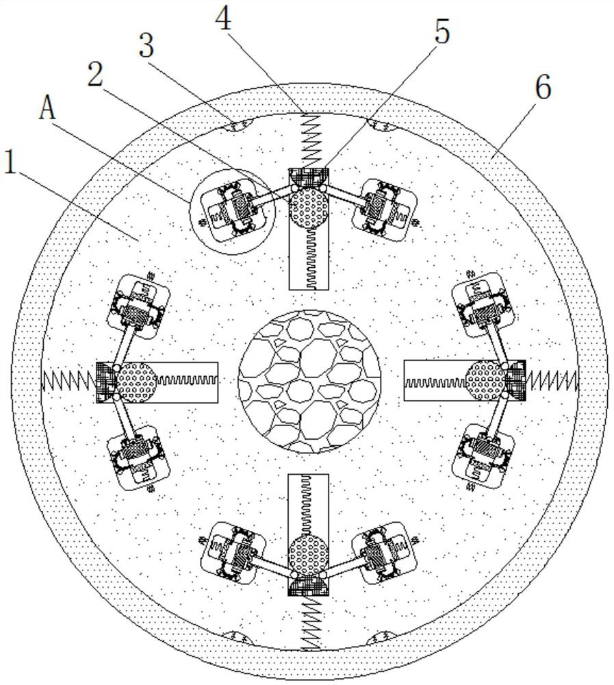
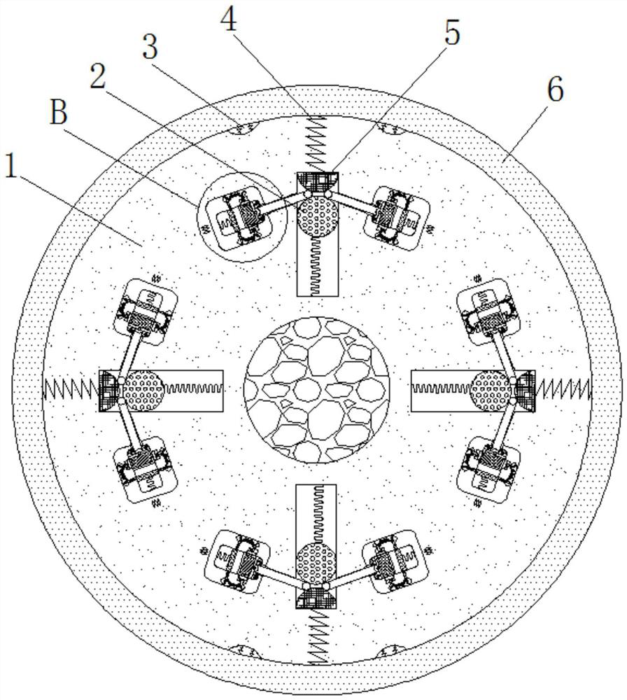
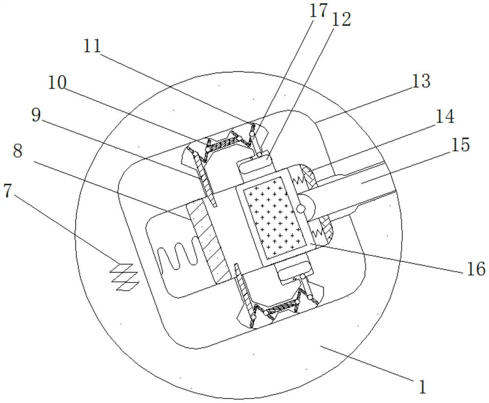
[0026] see Figure 1-4 , a conveying flattening device based on clothing fabric dyeing, comprising a roller shaft 1, a heating ring 6 is fixedly connected to the outer side of the roller shaft 1, the heating ring 6 is a cylindrical structure, the material of the heating ring 6 is copper, and the roller shaft 1 The inner wall of the roller shaft 1 is fixedly connected with a thermistor 3, the number of thermistor 3 is four, the thermistor 3 is evenly distribute...


PUM


Abstract

The invention relates to the technical field of clothing, and discloses a conveying and flattening device based on clothing fabric dyeing. The conveying and flattening device comprises a roller shaft,a heating ring is fixedly connected to the outer side of the roller shaft, a thermistor is fixedly connected to the inner wall of the roller shaft, a heat conducting wire is fixedly connected to theinner side of the roller shaft, and a connecting point is fixedly connected to the inner side of the heat conducting wire. According to the conveying and flattening device based on clothing fabric dyeing, an electric contact can be in contact with the connecting point under the action of centrifugal force of rotation of the roller shaft, a heat conducting wire can convert point energy into heat energy and transmit the heat energy to the heating ring, ironing of fabric is achieved, the wrinkled fabric is not wrinkled any more after being flattened by the roller shaft, the flatness of the surface of the fabric is improved, the fabric is prevented from being overlapped and bonded together in the dyeing process, the percent of pass of products is increased, the yield is increased, resources are saved, meanwhile, the drying degree of the flattened fabric is also improved, and the color of the fabric is guaranteed.

Description

technical field [0001] The invention relates to the technical field of clothing, in particular to a conveying and flattening device based on clothing cloth dyeing. Background technique [0002] With the improvement of living standards, people's requirements for clothing are getting higher and higher. There are various types of clothing on the market, and people have more and more choices. Therefore, the processing of clothing is becoming more and more strict. However, Clothing will go through the dyeing process during the processing process. Before dyeing, the fabric needs to be flattened and then transported to the dyeing pool. However, the effect of the existing flattening roller is not obvious, and the partially wrinkled fabric is flattened by the roller It will then return to its wrinkled state, making the fabric less dyed. [0003] The main reason for the insufficient dyeing of the cloth is that the folded cloth returns to its original folds after being flattened by th...

Claims


Application Information

Patent Timeline
IPC IPC(8): D06B23/04D06B23/02D06C15/08
CPCD06B23/02D06B23/04D06C15/08
Inventor 李霞芳
Owner 广州玉诚电子贸易有限公司
Why Eureka
Try Eureka