Automatic test circuit, automatic test instrument and automatic test system

An automatic test and circuit technology, applied in the electronic field, can solve the problems of inconvenient use of digital multimeters and low test efficiency, and achieve the effect of improving test efficiency and production efficiency

Active Publication Date: 2020-12-22
SHENZHEN TOP TEK ELECTRONICS CO LTD
View PDF4 Cites 6 Cited by
  • Summary
  • Abstract
  • Description
  • Claims
  • Application Information

AI Technical Summary

Problems solved by technology

[0003] In order to overcome the above-mentioned shortcomings of the prior art, the object of the present invention is to provide an automatic test circuit, which aims to solve the problems of inconvenient use and low test efficiency of existing digital multimeters

Method used


Image

  • Automatic test circuit, automatic test instrument and automatic test system
  • Automatic test circuit, automatic test instrument and automatic test system
  • Automatic test circuit, automatic test instrument and automatic test system

Examples


Embodiment 1

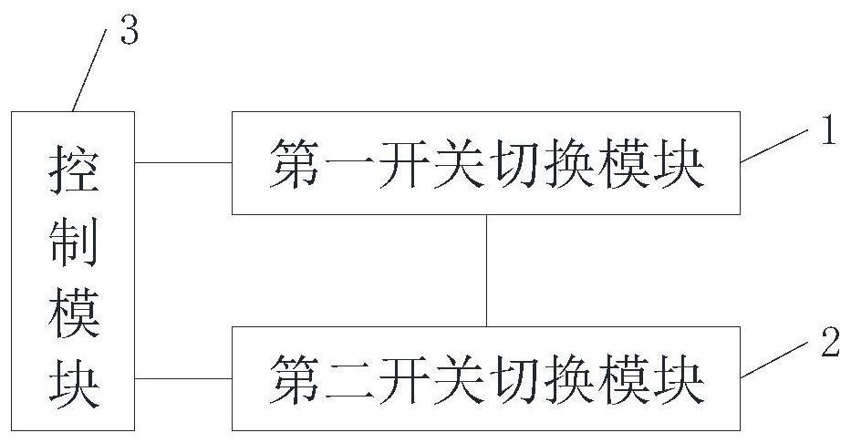
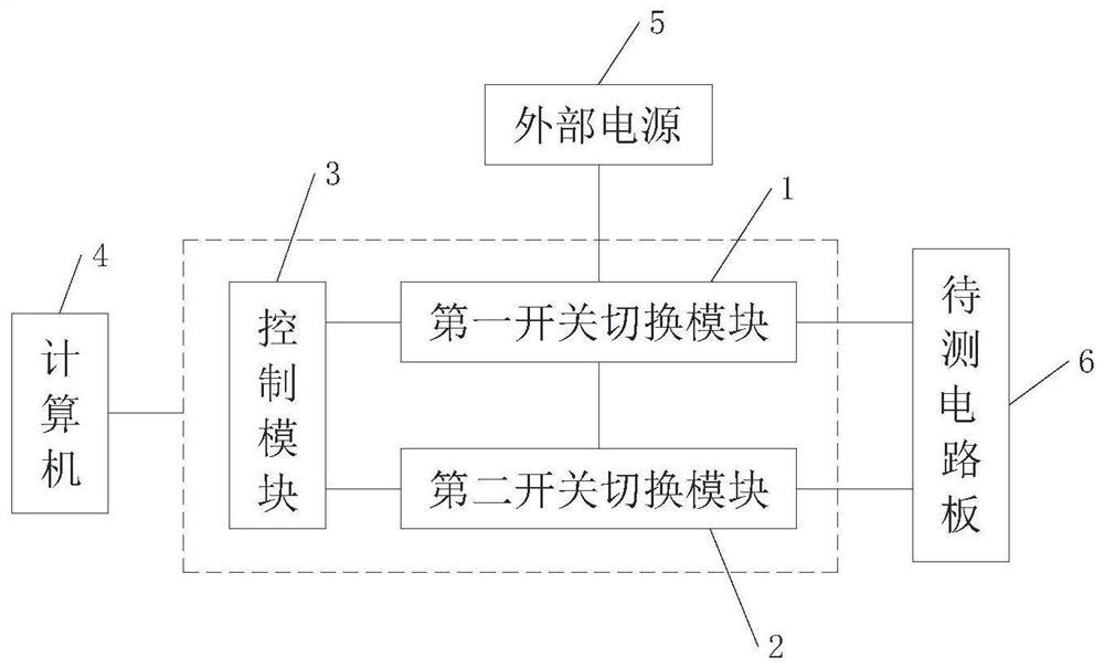
[0024] refer to figure 1 and figure 2 , the embodiment of the present invention provides an automatic test circuit, which is used to be connected to the computer 4, the external power supply 5, and the circuit board of the electronic product to be tested (ie, the circuit board to be tested 6). The automatic test circuit includes a first switch Module 1, the second switching module 2, and a control module 3 connected to the first switching module 1 and the second switching module 2 respectively, wherein the first switching module 1 has a positive and negative pole for connecting the external power supply 5 The power supply interface (not shown in the figure), and the circuit board interface (not shown in the figure) for connecting the positive and negative poles of the circuit board 6 to be tested; the second switching module 2 is connected with the first switching module 1 , and the second switch switching module 2 has a test lead interface (not shown in the figure) for conn...

Embodiment 2

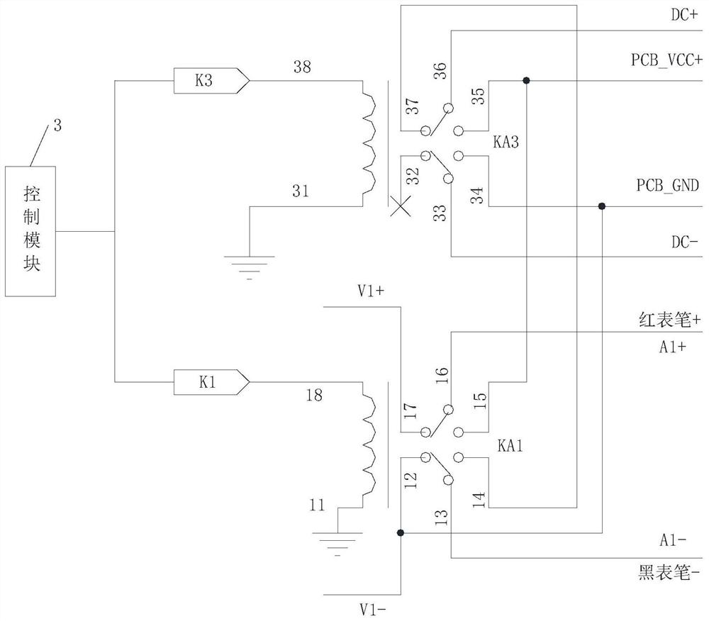
[0028] In a specific application scenario, when the operating voltage of only one group of voltage test points needs to be tested on the circuit board to be tested 6, the automatic test circuit in the embodiment of the present invention can adopt the following structural design: Specifically, refer to Figure 1 to Figure 3, the embodiment of the present invention provides an automatic test circuit for respectively connecting with a computer 4, an external power supply 5, and a circuit board to be tested 6. The automatic test circuit includes a first switch switching module 1, a second switch switching module 2 and A control module 3 connected to the first switching module 1 and the second switching module 2 respectively, the first switching module 1 includes a third double-pole double-throw relay KA3 and a third control switch K3, the second The switch switching module 2 includes a first double-pole double-throw relay KA1 and a first control switch K1, and the control module 3 ...

Embodiment 3

[0035] In another specific application scenario, when it is necessary to test the working voltage of more than two groups of voltage test points on the circuit board 6 to be tested, at least one second double-pole double-throw relay can be added on the basis of the second embodiment above KA2, wherein, when the number of the second double-pole double-throw relay KA2 is one, the operating voltage of the two groups of voltage test points on the circuit board 6 to be tested can be tested; when the second double-pole double-throw relay KA2 is newly added When the quantity is two, the operating voltages of the three groups of voltage test points on the circuit board 6 to be tested can be tested, and so on. It is possible to test the operating voltage of one more set of voltage test points. For the convenience of description, this embodiment takes two additional second double-pole double-throw relays KA2 as an example for illustration. Specifically, refer to figure 1 , figure 2 a...


PUM


Abstract

The invention discloses an automatic test circuit, an automatic test instrument and an automatic test system. The automatic test circuit comprises a first switch switching module, a second switch switching module, and a control module which is connected with the first switch switching module and the second switch switching module, wherein the first switch switching module is provided with a powerinterface used for connection of positive and negative electrodes of an external power supply and a circuit board interface used for connection of positive and negative electrodes of a to-be-tested circuit board; the second switch switching module is connected with the first switch switching module, and the second switch switching module is provided with a meter pen interface used for connection of the positive electrode and the negative electrode of a meter pen and at least one group of voltage test interfaces used for connection of at least one group of voltage test points located on the to-be-tested circuit board; and the control module is used for controlling the on-off state of the first switch switching module and / or the second switch switching module. The dynamic test circuit disclosed by the invention can solve the problems that an existing digital universal meter is inconvenient to use and low in test efficiency.

Description

technical field [0001] The invention belongs to the field of electronic technology, and in particular relates to an automatic test circuit, an automatic test instrument and an automatic test system. Background technique [0002] In the functional test of electronic products, it is often necessary to measure the current and the working voltage of related test points under various working conditions without power supply. At present, digital multimeters are generally used to measure various parameters such as current and voltage of electronic products. However, traditional digital During the use of the multimeter, it is necessary to manually adjust the measurement items and range, which is very troublesome and greatly reduces the test efficiency. Contents of the invention [0003] In order to overcome the above-mentioned shortcomings of the prior art, the object of the present invention is to provide an automatic test circuit, aiming at solving the problems of inconvenient us...

Claims


Application Information

Patent Timeline
Patent Type & Authority Applications(China)
IPC IPC(8): G01R31/28G01R15/12G01R1/067G01R1/04
CPCG01R31/2803G01R31/2808G01R15/12G01R1/067G01R1/0416
Inventor 刘小雄林海亮罗光辉周勤勉
Owner SHENZHEN TOP TEK ELECTRONICS CO LTD
Why Eureka
Try Eureka