A new energy vehicle charging socket assembly
A technology of new energy vehicles and charging sockets, which is applied in the direction of electric vehicle charging technology, charging stations, electric vehicles, etc., can solve the problems of inconvenient charging of new energy vehicles, inconvenience, and affecting the work arrangements of new energy vehicle users, so as to improve the use of Experience, improve practicability, and ensure the effect of normal charging
- Summary
- Abstract
- Description
- Claims
- Application Information
AI Technical Summary
Problems solved by technology
Method used
Image
Examples
Embodiment 1
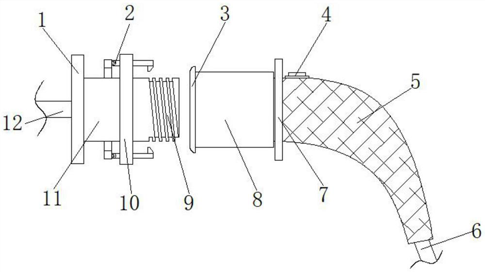
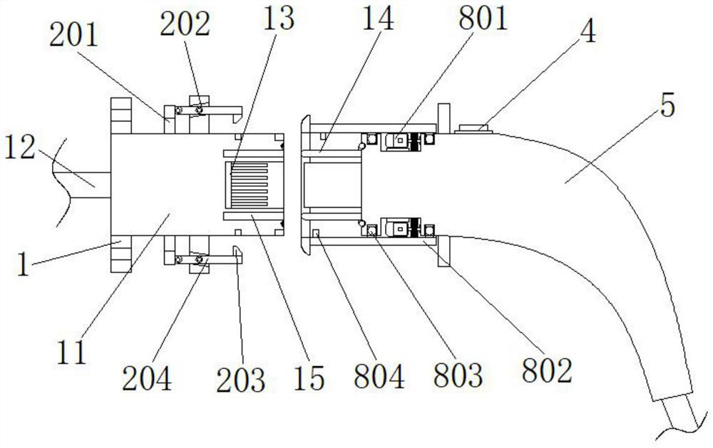
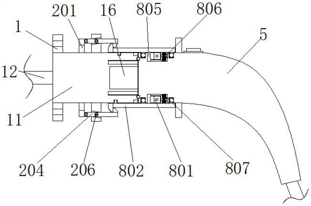
[0032] Example 1, such as Figure 1-5 As shown, when a user of a new energy vehicle charges the vehicle, he manually holds the outside of the charging tube 5, and inserts the two sets of insertion rods 14 into the two sets of slots 15 on the connecting base 11, so that the charging head 16 can be aligned and inserted into the inside of the charging slot 13. During the process, two groups of clamping blocks 804 are stuck in the bayonet sockets connected with the double helical groove 9, and then the two groups of micro servo motors 801 are controlled to rotate clockwise synchronously through the control panel 4, and the Through the cooperation of the gear 806 and the ring rack 807, the casing 802 is also driven to rotate clockwise, and the two sets of blocks 804 move into the inner side of the double helical groove 9 through the bayonet rotation, and the inserting rod 14 will be gradually inserted into the slot 15. Inserting into the slot 15, the charging tube 5 gradually appro...
Embodiment 2
[0033] Example 2, such as figure 1 , 2 , 3, 6 and 7, when the new energy vehicle user needs to leave the vicinity of the vehicle, in order to prevent outsiders from separating the charging tube 5 from the connecting seat 11, the miniature electric lifting rod 205 can be controlled by the control button on the main console elongate, forcing the two groups of movable rods 204 to rotate 15° with the movable shaft 206 as the axis, so that the movable rods 204 are parallel to the outside of the connecting seat 11, and at this time, the anti-tripping buckle 203 is stuck on the limit ring 3 away from the mounting ring 10. On one side, the position of the self-inserting assembly 8 is limited to prevent the charging tube 5 from being separated from the connection base 11 .
[0034] Working principle: Connect the device to the power supply before use, first fix all the parts connected to the connecting seat 11 to the charging interface of the new energy vehicle through the fixing screw...
PUM
 Abstract
Description
Claims
Application Information
 - R&D
- Intellectual Property
- Life Sciences
- Materials
- Tech Scout
- Unparalleled Data Quality
- Higher Quality Content
- 60% Fewer Hallucinations
Browse by: Latest US Patents, China's latest patents, Technical Efficacy Thesaurus, Application Domain, Technology Topic, Popular Technical Reports.
© 2025 PatSnap. All rights reserved.Legal|Privacy policy|Modern Slavery Act Transparency Statement|Sitemap|About US| Contact US: help@patsnap.com


