Multifunctional self-extinguishing ashtray which is convenient to carry and clean
An ashtray and multifunctional technology, applied in the field of ashtrays, can solve the problems of inconvenient portability of ashtrays, inconvenient cigarette butts to be extinguished, inconvenient to collect ash, etc., and achieve the effect of being easy to carry and clean.
- Summary
- Abstract
- Description
- Claims
- Application Information
AI Technical Summary
Problems solved by technology
Method used
Image
Examples
Embodiment 1
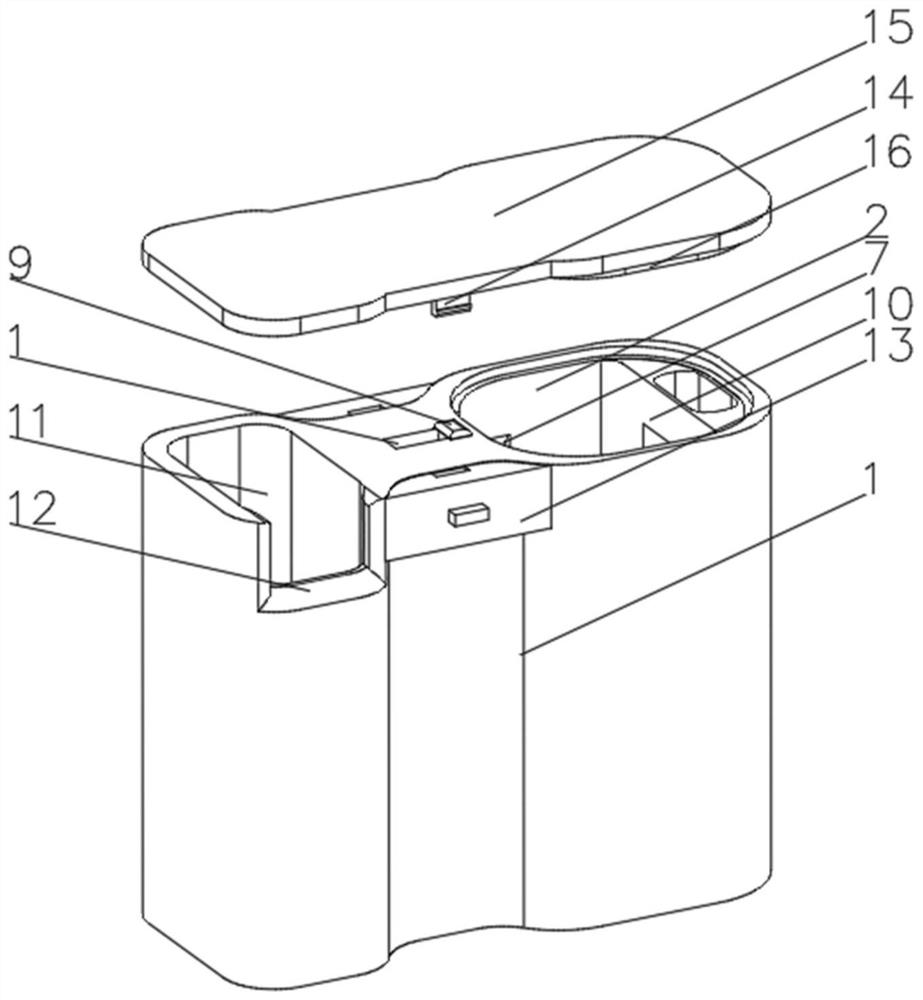
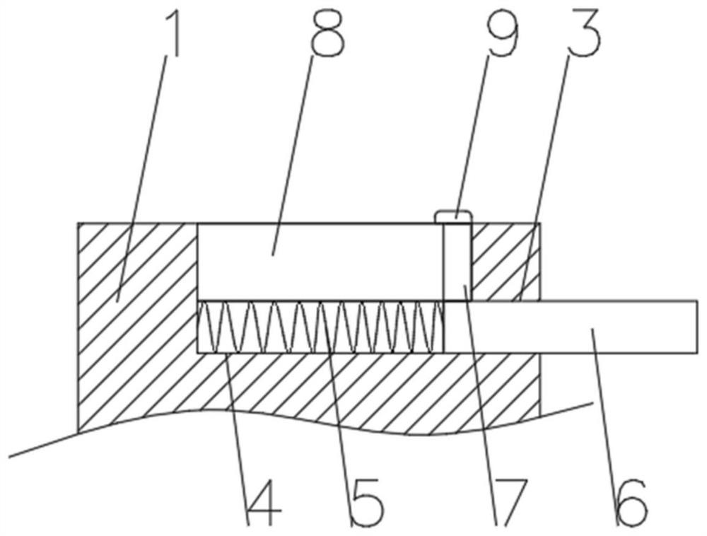
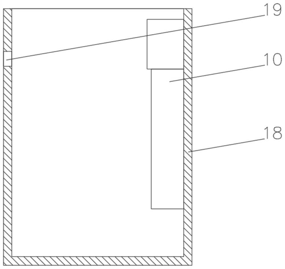
[0032] see Figure 1-5, the present invention provides a technical solution: a multifunctional self-extinguishing ashtray that is easy to carry and clean, including an ashtray body 1, an ashtray 2 is provided at the top end of the ashtray body 1, and an ashtray is slidably connected to the inner wall of the ashtray 2 18. There is a flat chute 3 on one side of the top of the soot chute 2, and an elastic chute 4 is opened on the bottom of the inner wall of the flat chute 3. The bottom of the inner wall of the elastic chute 4 is fixedly connected with a return spring 5, and the return spring 5 is far away from the inner wall of the elastic chute 4. One end of the bottom extends to the inside of the flat chute 3 and is fixedly connected with an ash plate 6 , the ash plate 6 is slidably connected to the inner wall of the flat chute 3 , and the side of the ash plate 6 away from the return spring 5 extends to the outside of the flat chute 3 , the top of the ashtray 6 is fixedly conne...
Embodiment 2
[0034] see Figure 1-6 On the basis of Embodiment 1, the present invention provides a technical solution: the smoke extinguishing device 10 includes a support base 1001, a smoke extinguishing tank 1002 is provided on the top of the support base 1001, and a soot cleaning hole 1003 is provided on one side of the smoke extinguishing tank 1002, supporting The bottom of the seat 1001 runs through and is fixedly connected with a support cylinder 1004. The bottom of the inner wall of the support cylinder 1004 is provided with a fixed groove 1005. The inner wall of the fixed groove 1005 is fixedly connected with a rubber sleeve 1006. The inner wall of the rubber sleeve 1006 is slidingly connected with a fixed rod 1007. A bottom plate 1008 is connected, and a compression spring 1009 is fixedly connected to the top of the bottom plate 1008. The end of the compression spring 1009 away from the bottom plate 1008 is fixedly connected to a top plate 1010, and the side of the top plate 1010 c...
PUM
 Abstract
Description
Claims
Application Information
 - R&D
- Intellectual Property
- Life Sciences
- Materials
- Tech Scout
- Unparalleled Data Quality
- Higher Quality Content
- 60% Fewer Hallucinations
Browse by: Latest US Patents, China's latest patents, Technical Efficacy Thesaurus, Application Domain, Technology Topic, Popular Technical Reports.
© 2025 PatSnap. All rights reserved.Legal|Privacy policy|Modern Slavery Act Transparency Statement|Sitemap|About US| Contact US: help@patsnap.com


