
Sawing machine dynamic adjustment clamping guide structure

A technology of guiding structure and dynamic adjustment, applied in the field of sawing machines, can solve the problems of sawing efficiency, sawing quality, impact of saw blade life, sawing skew, and low efficiency, so as to reduce abnormal consumption and realize dynamic sawing. , The effect of improving sawing efficiency

Pending Publication Date: 2020-12-25
郑钧东
View PDF0 Cites 0 Cited by
  • Summary
  • Abstract
  • Description
  • Claims
  • Application Information

AI Technical Summary

Problems solved by technology

[0004] This method will not have a great impact on the sawing of the sawing machine in a short period of time, but after a long time of sawing, the upper tungsten steel and the saw blade will have corresponding wear, so that the gap between the upper tungsten steel and the saw blade will become larger, which will cause damage to the user. Saw sawing, broken belt, low efficiency, etc.
[0005] Moreover, the device will not automatically switch the cutting speed with the change of the material or the fatigue of the saw blade. All operations are manually adjusted based on the operator's personal actual operating experience, so it will have an impact on sawing efficiency, sawing quality, and saw blade life.

Method used


Image

  • Sawing machine dynamic adjustment clamping guide structure

Examples


Embodiment

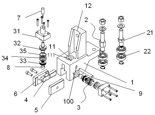
[0020] A sawing machine dynamic adjustment clamping guide structure, such as figure 1 As shown, it includes a guide seat 1 and a locking adjustment structure 3 arranged on the upper side and the right side of the front end of the guide seat 1 .

[0021] At the action end, the locking adjustment structure 3 is respectively connected with the tungsten steel 4 and the right tungsten steel 5 on the upper side and the right side inside the front end of the guide seat 1. Tungsten steel 6, the left and right tungsten steel are used to clamp the saw blade to prevent it from lateral deviation, and the upper tungsten steel can press the saw blade.

[0022] Specifically, the upper tungsten steel 4 has a vertical degree of freedom in the guide seat 1, and the realization of this degree of freedom is that the guide seat 1 is provided with a vertical strip-shaped connecting groove 100 for the parallel pin 9, and the parallel pin 9 The upper tungsten steel 4 is connected in the guide seat 1...


PUM


Abstract

The invention discloses a sawing machine dynamic adjustment clamping guide structure. The structure comprises a guide seat and locking adjustment structures arranged on the upper side and the right side of the front end of the guide seat, wherein the locking adjustment structures are connected with upper tungsten steel and right tungsten steel on the upper side and the right side inside the frontend of the guide seat respectively, left tungsten steel is arranged on the left side in the front end of the guide seat and corresponds to the right tungsten steel, and the upper tungsten steel has avertical degree of freedom in the guide seat; guide structures are arranged at the rear end of the guide seat side by side; the locking adjusting structures comprise oil cylinders, pressing pistons and butterfly reeds, wherein the pressing pistons are arranged in the oil cylinders, and the butterfly reeds sleeve the pressing pistons; and a displacement sensor is arranged on the oil cylinder of thelocking adjusting structure on the upper side and acts on a piston rod of the corresponding pressing piston. According to the sawing machine dynamic adjustment clamping guide structure, the oil cylinders and the displacement sensor cooperate together, and compared with the mode that the descending speed is manually adjusted in the past, intelligence of a sawing machine is greatly achieved throughthe above innovation and optimization, so that the sawing efficiency and the sawing quality are remarkably improved, and unusual consumption is reduced.

Description

technical field [0001] The invention relates to the field of sawing machines, in particular to a dynamic adjustment clamping and guiding structure for sawing machines. Background technique [0002] At present, the mainstream saw blade guide and clamping of sawing machines mainly use two main methods: clamping rollers and clamping tungsten steel sheets. [0003] In terms of the clamping method of tungsten steel, the currently widely used adjustment method is manual one-time adjustment and positioning, even if the upper tungsten steel is close to the back of the saw blade, so as to offset the upward pressure from sawing during sawing. [0004] This method will not have a great impact on the sawing of the sawing machine in a short period of time, but after a long time of sawing, the upper tungsten steel and the saw blade will have corresponding wear, so that the gap between the upper tungsten steel and the saw blade will become larger, which will affect the user. Sawing saw sk...

Claims


Application Information

Patent Timeline
Patent Type & Authority Applications(China)
IPC IPC(8): B23D59/00
CPCB23D59/00
Inventor 郑钧东
Owner 郑钧东
Learn More