
Breakage-proof device for drilling thin-wall pipe fitting

A pipe fitting and thin-walled technology, which is applied in the field of anti-damage devices for drilling thin-walled pipe fittings, and can solve problems such as potential safety hazards, drilling position deviation, and waste of pipe fittings

Inactive Publication Date: 2020-12-25
GUANGZHOU JUSANLIUSHA TECH CO LTD
View PDF0 Cites 2 Cited by
  • Summary
  • Abstract
  • Description
  • Claims
  • Application Information

AI Technical Summary

Problems solved by technology

[0002] Pipe fittings are a general term for components that play the roles of connection, control, direction change, diversion, sealing, support, etc. in the pipeline system. With the development of the current society, more and more power pipelines and water conservancy pipelines are laid. In actual use, sometimes it is necessary to open a reserved through hole at the end of the pipe as the connection unit of the branch pipe, but when the traditional pipe is drilled at the joint, the staff usually supports the pipe fittings, and then directly uses the drill Hole equipment is used to punch holes on the pipeline. Due to the lack of effective protective equipment, the pipe fittings are easily damaged during the drilling process, resulting in waste of pipe fittings, and due to the radial stress on the pipe fittings during the drilling process is also easy The pipe wall structure of the pipe fittings is damaged to a certain extent, so that the overall strength of the pipe is affected, leaving certain safety hazards
[0003] Thin-walled pipe fittings refer to pipe parts whose wall thickness to outer diameter ratio is not more than 6%. In the process of drilling, there is no good device for fixing the structure of the pipe fittings, which leads to the deviation of the drilling position of the pipe fittings during the actual drilling process, which affects the accuracy of the drilling

Method used


Image

  • Breakage-proof device for drilling thin-wall pipe fitting
  • Breakage-proof device for drilling thin-wall pipe fitting
  • Breakage-proof device for drilling thin-wall pipe fitting

Examples


Embodiment Construction

[0025] The following will clearly and completely describe the technical solutions in the embodiments of the present invention with reference to the accompanying drawings in the embodiments of the present invention. Obviously, the described embodiments are only some, not all, embodiments of the present invention. Based on the embodiments of the present invention, all other embodiments obtained by persons of ordinary skill in the art without making creative efforts belong to the protection scope of the present invention.

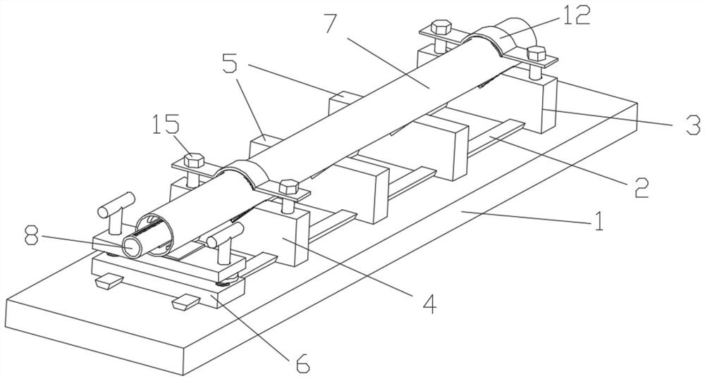
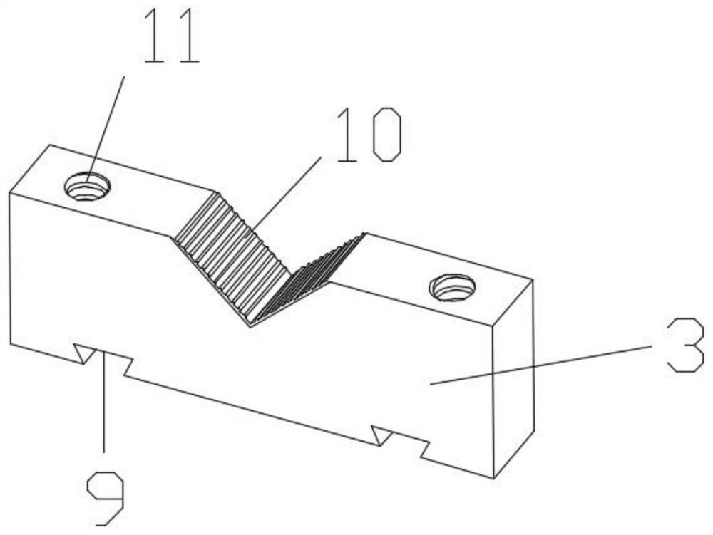
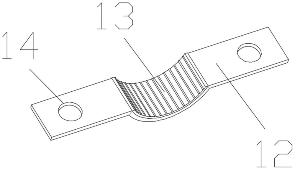
[0026] see Figure 1-6 , the present invention provides a technical solution: an anti-damage device for drilling thin-walled pipe fittings, including a base 1 and a guide rail 2 arranged on the base 1, the base 1 is a rectangular seat, and the guide rails 2 are arranged symmetrically on the base 1 There is one group, and the section of the guide rail 2 is an inverted trapezoid, the rear end of the base 1 is provided with a first-level fixing seat 3, the front ...


PUM


Abstract

The invention discloses a breakage-proof device for drilling a thin-wall pipe fitting. The device comprises a base and guide rails arranged on the base, wherein the base is a rectangular base body, the set of guide rails are symmetrically arranged on the base, a section of each guide rail is in an inverted trapezoid shape, a first-stage fixing base is arranged at the rear end of the base, a second-stage fixing base is arranged at the position, close to the front end, of the base, a supporting base is arranged at the front end of the second-stage fixing base, first-stage guide rail grooves areformed in the lower surfaces of the first-stage fixing base, sizes of the first-stage guide rail grooves match that of a section of each guide rail, the first-stage guide rail grooves correspond to the guide rails in position, the first-stage fixing base is arranged on the guide rails in a sliding mode through the first-stage guide rail grooves, a structure of the second-stage fixing base is sameas that of the first-stage fixing base, and a group of bolt holes are symmetrically formed in the upper surfaces of each of the first-stage fixing base and the second-stage fixing base. By arranging an inner supporting structure, the inner supporting structure extends into a pipe fitting cavity, the pipe fitting is supported from the interior of the pipe fitting cavity, so that the situation thatthe side wall of the pipe fitting is excessively stressed and therefore damaged due to a pressure of the pipe fitting in a drilling operation process is avoided.

Description

technical field [0001] The invention relates to the technical field of drilling of pipe fittings, in particular to an anti-damage device for drilling of thin-walled pipe fittings. Background technique [0002] Pipe fittings are a general term for components that play the roles of connection, control, direction change, diversion, sealing, support, etc. in the pipeline system. With the development of the current society, more and more power pipelines and water conservancy pipelines are laid. In actual use, sometimes it is necessary to open a reserved through hole at the end of the pipe as the connection unit of the branch pipe, but when the traditional pipe is drilled at the joint, the staff usually supports the pipe fittings, and then directly uses the drill Hole equipment is used to punch holes on the pipeline. Due to the lack of effective protective equipment, the pipe fittings are easily damaged during the drilling process, resulting in waste of pipe fittings, and due to t...

Claims


Application Information

Patent Timeline
IPC IPC(8): B23Q3/06
CPCB23Q3/064B23Q3/065
Inventor 梁艳英
Owner GUANGZHOU JUSANLIUSHA TECH CO LTD
Learn More