Controllable one-way clutch

A one-way clutch and standard technology, applied in the field of clutches, can solve the problems of selecting the direction of transmission, inability to control the opening and closing of the one-way rotation function, etc., and achieve a wide range of applications.

Pending Publication Date: 2020-12-25
SHUNDE POLYTECHNIC
0 Cites 0 Cited by

AI-Extracted Technical Summary

Problems solved by technology

[0004] However, the above-mentioned controllable one-way clutch cannot control the opening and closing of the one-way rotation function, and usually can only be transmitted in a certain direction (...

Method used

More specifically, the inner peripheral wall 10 of the outer ring 1 is set to the surface of the cam profile, and the surface shape of the cam profile is satisfied at the small end and the roller can be locked...

Abstract

The invention discloses a controllable one-way clutch. The controllable one-way clutch comprises an inner ring, an outer ring, a roller control ring and a roller, and further comprises a control sleeve, wherein rectangular gaps are formed in the two ends of the outer ring to form a separation cavity; the roller control ring is provided with a right-angled trapezoidal limiting block and a roller hole; a separating block in an inverted right trapezoid shape is arranged at the inner circumferential wall of the control sleeve; one side of a bevel of the limiting block and one side of a bevel of the separation block are installed in a separation cavity in a paired manner; a spring is arranged at one side of the right-angled side of the limiting block and abuts against the side wall of the separation cavity; when the separating block axially moves deep into a space between the limiting block and the separation cavity, the limiting block moves to enable the roller not to make contact with theinner ring and/or the outer ring, and thus the one-way transmission function is stopped. The controllable one-way clutch disclosed by the invention can control start and stop of the one-way transmission function thereof and achieves good operation stability.

Application Domain

Freewheel clutches

Technology Topic

ClutchRight trapezoid +1

Image

  • Controllable one-way clutch
  • Controllable one-way clutch
  • Controllable one-way clutch

Examples

  • Experimental program(1)

Example Embodiment

[0018]The technical solution will be described in detail below in conjunction with specific embodiments.
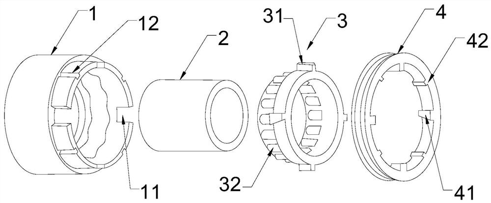
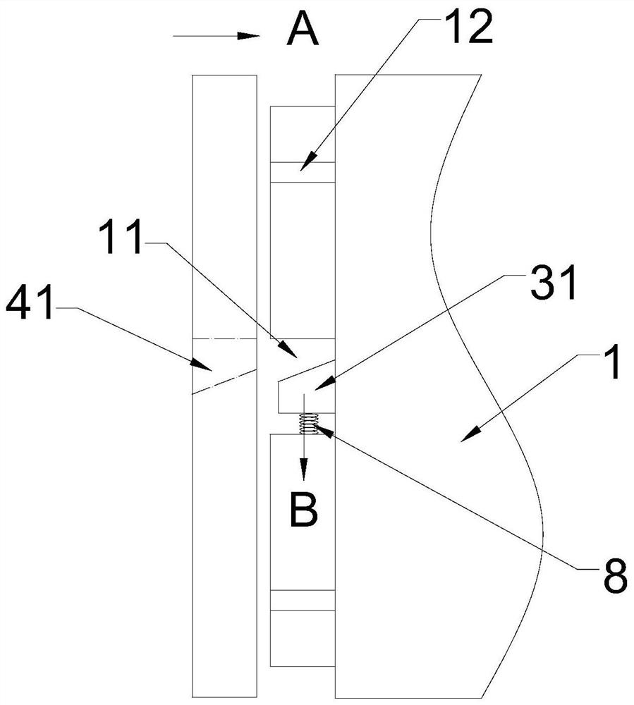
[0019]Such asFigure 1-5As shown, the present invention is a controllable one-way clutch, including a control sleeve 4, a roller control ring 3, an inner ring 2 and an outer ring 1, wherein the roller control ring 3 includes a square roller hole 32, a roller 7. The inner ring 2 is arranged inside the outer ring 1. A set of control sleeve 4 and a roller control ring 3 are arranged at one end of the inner and outer ring. The roller control ring 3 is axially sleeved with an inner ring 2 and an axial outer ring 1. The roller The control ring 3 is provided with a roller hole 32, and the roller 7 is mounted on the roller hole 32. One end of the roller 7 abuts against the outer peripheral wall of the inner ring 2, and the other end abuts against the inner peripheral wall 10 of the outer ring 1. .
[0020]The connecting part of the roller control ring 3 is also installed with a right-angle trapezoidal stopper 31, a control sleeve 4 is axially provided on the outer circumference of the roller control ring 3, and the inner peripheral wall of the control sleeve 4 is provided with several groups The separation block 41 in the shape of an inverted right-angle trapezoid is provided with square notches on the connecting walls 13 at both ends of the outer ring 1 to form the separation cavity 11. The right-angle side of the limit block is provided with a spring 8 and presses against the side wall of the separation chamber. The control sleeve 4 can move axially. When the separation block 41 on it axially penetrates into the space between the limit block 31 and the separation chamber 11, the limit The position block 31 moves so that the roller 7 is out of contact with the outer ring 1. When the separation block 41 axially draws out the space between the limit block 31 and the separation cavity 11, the spring moves the limit block 31 so that the roller 7 and the inner ring 2 is in contact with outer ring 1, and the one-way transmission function is activated.
[0021]More specifically, the inner peripheral wall of the control sleeve 4 is further provided with several sets of guide sliders 42, the guide sliders 42, and the connecting wall 13 of the outer ring 1 is also provided with positioning chutes 12, the guide slider 42 and the positioning chutes 12 Sliding connection, that is, the control sleeve 4 can move axially along the connecting wall 13 on the outer ring 1.
[0022]More specifically, the control sleeve 4 and the roller control ring 3 are arranged on the clutch.
[0023]More specifically, the inner peripheral wall 10 of the outer ring 1 is set as a cam profile surface. The surface of the cam profile meets the shape of the small end to lock the rollers, ensuring the follow-up of the inner ring 2 and the outer ring 1, and the large end has enough The space can allow the rollers to rotate to ensure the separation of the inner ring 2 and the outer ring 6.
[0024]In this embodiment, the present invention has two working states of the one-way transmission function closed and opened. When the one-way transmission function of the controllable one-way clutch is in the open state, the control sleeve 4 on the controllable one-way clutch Moving outward along the connecting wall 13 of the outer ring 1, the separation block 41 on the control sleeve 4 is separated from the separation cavity 11, and the limit block 31 is pushed by the spring 8 to make the roller control ring 3 rotate counterclockwise to a certain angle, One end of the roller 7 abuts the inner ring 2, and the other end of the roller 7 abuts the convex surface (commonly known as the small end) on the inner peripheral wall of the outer ring 1. When the inner ring 2 rotates counterclockwise, the inner ring 2 can be realized. Drive the power transmission of the outer ring 1; when the inner ring 2 rotates clockwise, the roller spring will pull the roller up the concave surface (commonly known as the big end). At this time, the roller 7 is separated from the outer ring 1, that is, the inner ring 2 and the outer ring Circle 1 is disengaged and no power transmission occurs.Figure 5 The roller spring is not shown.
[0025]When the control sleeve 4 on the controllable one-way clutch moves along the connecting wall 13 of the outer ring 1 to the outer ring, the separation block 41 on the control sleeve 4 penetrates into the separation cavity 11. Since the contact surface of the separation block is an inclined surface, the limit block 31 is squeezed by the separating block 41 to squeeze the spring 8, thereby pushing the roller control ring 3 to rotate clockwise to a certain angle. One side of the roller 7 presses the inner ring 2, and the other side of the roller 7 is not in contact with the outer ring 1. The inner peripheral wall 10 contacts, the one-way transmission function is closed. That is, to control the control sleeve on the right side of the controllable one-way clutch, two outputs can be realized: 1) The control sleeve is separated from the separation cavity and one-way transmission; 2) The control sleeve is inserted into the separation cavity and the one-way transmission function is closed.
[0026]The above are only the preferred embodiments of the present invention. It should be pointed out that for those of ordinary skill in the art, without departing from the inventive concept of the present invention, several modifications and improvements can be made, all of which belong to the present invention. The scope of protection.

PUM

no PUM

Description & Claims & Application Information

We can also present the details of the Description, Claims and Application information to help users get a comprehensive understanding of the technical details of the patent, such as background art, summary of invention, brief description of drawings, description of embodiments, and other original content. On the other hand, users can also determine the specific scope of protection of the technology through the list of claims; as well as understand the changes in the life cycle of the technology with the presentation of the patent timeline. Login to view more.

Similar technology patents

Classification and recommendation of technical efficacy words

Why Eureka
Try Eureka