Supercharge Your Innovation With Domain-Expert AI Agents!

Novel spiral transmission mechanism

A new type of screw drive technology, applied in the direction of transmission, transmission parts, mechanical equipment, etc., can solve the problems of fast wear, difficult processing, complex rolling screw drive structure, etc.

Inactive Publication Date: 2020-12-25
CHINA AVIATION OPTICAL-ELECTRICAL TECH CO LTD
View PDF6 Cites 2 Cited by
  • Summary
  • Abstract
  • Description
  • Claims
  • Application Information

AI Technical Summary

Problems solved by technology

[0003] Sliding screw transmission is to use the thread pair (the nut is processed as an internal thread, and the screw is processed as an external thread) as a transmission and load-bearing screw mechanism. It has the advantages of simple structure and convenient processing, but it needs regular lubrication, and the frictional resistance is large and the transmission efficiency is low. , fast wear
[0004] The rolling screw transmission is also called the ball screw pair. Balls are placed between the screw and the nut. When the screw or the nut rotates, the balls roll along the spiral raceway, so that there is rolling friction between the screw and the nut, which reduces the frictional resistance. The transmission efficiency is improved, but because the ball needs to return the device, the structure of the rolling screw transmission is complicated, the processing is difficult, and the size is large

Method used


Image

  • Novel spiral transmission mechanism
  • Novel spiral transmission mechanism
  • Novel spiral transmission mechanism

Examples


Embodiment Construction

[0031] In order to further explain the technical means and effects that the present invention adopts to achieve the intended purpose of the invention, the specific implementation, structure, characteristics and effects of the new screw transmission mechanism proposed according to the present invention will be described below in conjunction with the accompanying drawings and preferred embodiments. , as detailed below.

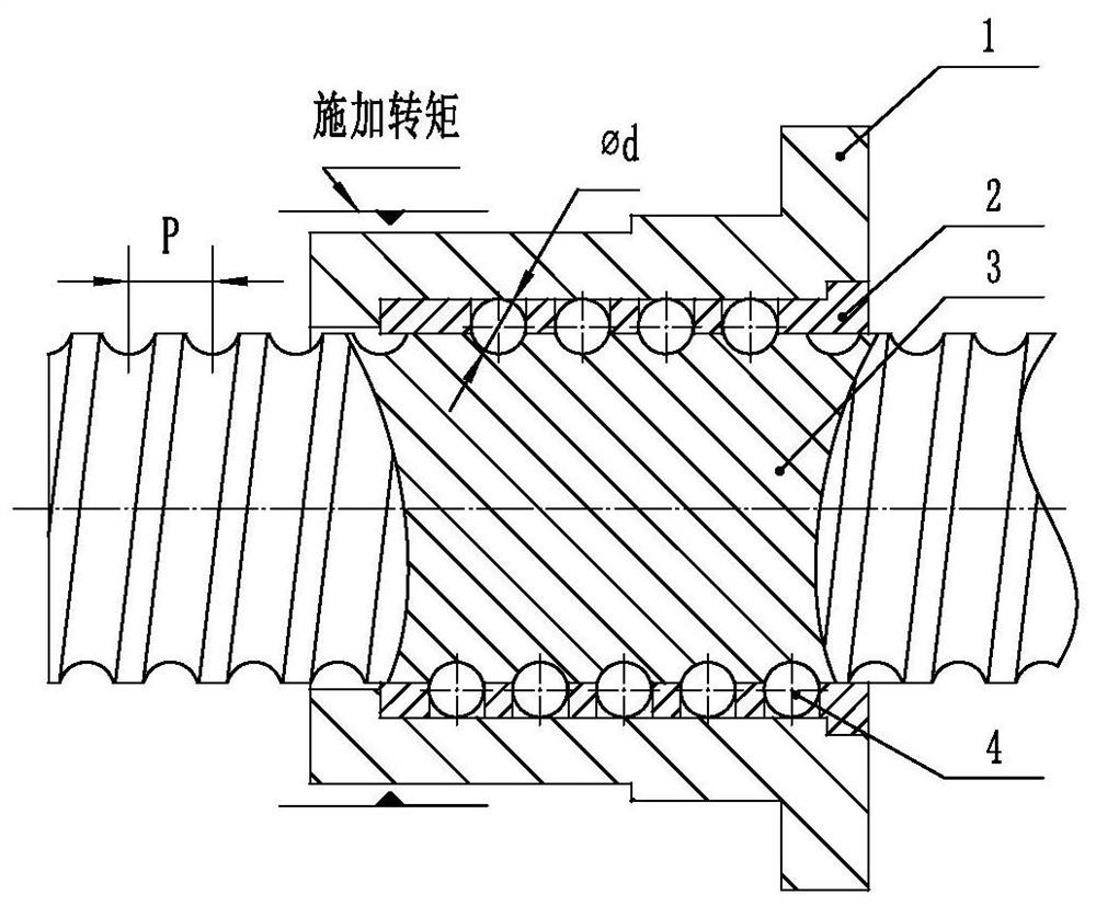
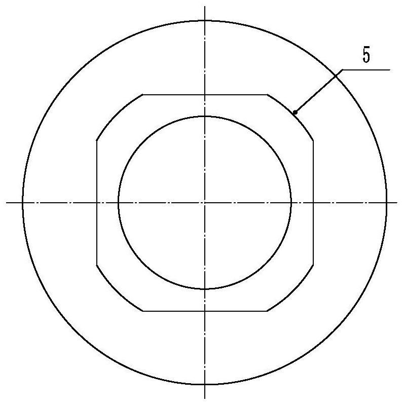
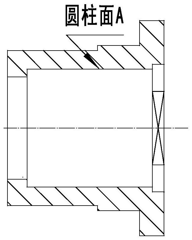
[0032] see Figure 1-7 , which is a structural schematic diagram of each part of the new screw transmission mechanism of the present invention, the new screw transmission mechanism includes a nut 1 for receiving external torque, a fixed sleeve fixedly assembled in the nut 1 and capable of transmitting the external torque received by the nut 1 2 and the screw 3 that passes through the fixed sleeve and rotates with the fixed sleeve to convert the torque into an axial load. The screw 3 plays the role of converting the torque into an axial load. The structural featu...


PUM


Abstract

The invention relates to a novel spiral transmission mechanism which comprises a nut, a fixing sleeve fixedly assembled in the nut, and a screw rod which penetrates through the fixing sleeve and is inrunning fit with the fixing sleeve. A track formed by a plurality of rows of through holes which are distributed at equal intervals along the axial direction and are provided with balls on the fixingsleeve is consistent with a spiral raceway of the screw rod; and when the nut receives external torque, the balls rotating along the spiral raceway along with the fixing sleeve under the constraint of the inner circumferential cylindrical surface of the nut and the spiral raceway of the screw rod provides power for the axial movement of the screw rod. According to the novel spiral transmission mechanism provided by the invention, the movement of the balls along the spiral raceway is not pure sliding friction or pure rolling friction, and the friction property of the balls depends on the roughness of a screw rod raceway, a mounting hole in the fixing sleeve and a cylindrical surface A in the nut. As the surfaces of the balls are smooth, the friction coefficient smaller than the friction coefficient of thread pair transmission can be obtained. Therefore, the transmission efficiency of spiral transmission of the structure is between the transmission efficiency of sliding spiral transmission and the transmission efficiency of rolling spiral transmission.

Description

technical field [0001] The invention belongs to the technical field of mechanical transmission, and in particular relates to a novel screw transmission mechanism. Background technique [0002] The screw drives used in engineering can be divided into sliding screw drive, rolling screw drive and hydrostatic screw drive according to the friction properties. Because the static pressure screw drive needs a set of oil supply system with stable pressure, constant temperature and high filtration requirements, it takes up a lot of space. Due to its large volume, hydrostatic screw drives are generally used in specific occasions that have extremely high requirements for transmission efficiency, and the application range is limited, so it is not considered. [0003] Sliding screw transmission is to use the thread pair (the nut is processed as an internal thread, and the screw is processed as an external thread) as a transmission and load-bearing screw mechanism. It has the advantages of...

Claims


Application Information

Patent Timeline
Patent Type & Authority Applications(China)
IPC IPC(8): F16H25/22F16H25/24F16H57/04
CPCF16H25/2204F16H25/24F16H57/0497
Inventor 陈继利庞卓陈杰
Owner CHINA AVIATION OPTICAL-ELECTRICAL TECH CO LTD
Features
  • R&D
  • Intellectual Property
  • Life Sciences
  • Materials
  • Tech Scout
  • Unparalleled Data Quality
  • Higher Quality Content
  • 60% Fewer Hallucinations
Learn More