Gear lubricating structure, gear and gearbox

A lubricating structure and gear technology, applied in gear lubrication/cooling, belt/chain/gear, components with teeth, etc., can solve problems such as poor heat dissipation

Pending Publication Date: 2020-12-25
GREE ELECTRIC APPLIANCES INC
View PDF0 Cites 0 Cited by
  • Summary
  • Abstract
  • Description
  • Claims
  • Application Information

AI Technical Summary

Problems solved by technology

[0004] The purpose of this application is to provide a gear lubrication structure, gear and gearbox to solve the problem of poor gear lubrication and heat dissipation in the prior art

Method used


Image

  • Gear lubricating structure, gear and gearbox
  • Gear lubricating structure, gear and gearbox
  • Gear lubricating structure, gear and gearbox

Examples


Embodiment Construction

[0032] In order to make the purpose, technical solutions and advantages of the embodiments of the present invention clearer, the technical solutions in the embodiments of the present invention will be clearly and completely described below in conjunction with the drawings in the embodiments of the present invention. Obviously, the described embodiments It is a part of embodiments of the present invention, but not all embodiments. Based on the embodiments of the present invention, all other embodiments obtained by persons of ordinary skill in the art without making creative efforts belong to the protection scope of the present invention.

[0033] Below in conjunction with accompanying drawing and specific embodiment the present invention is described in further detail:

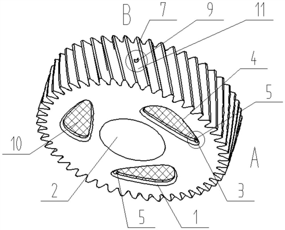
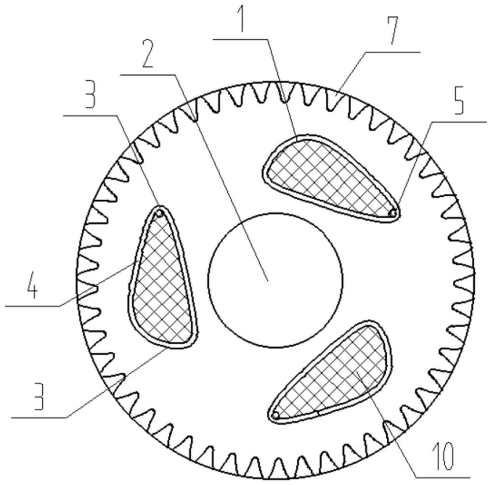
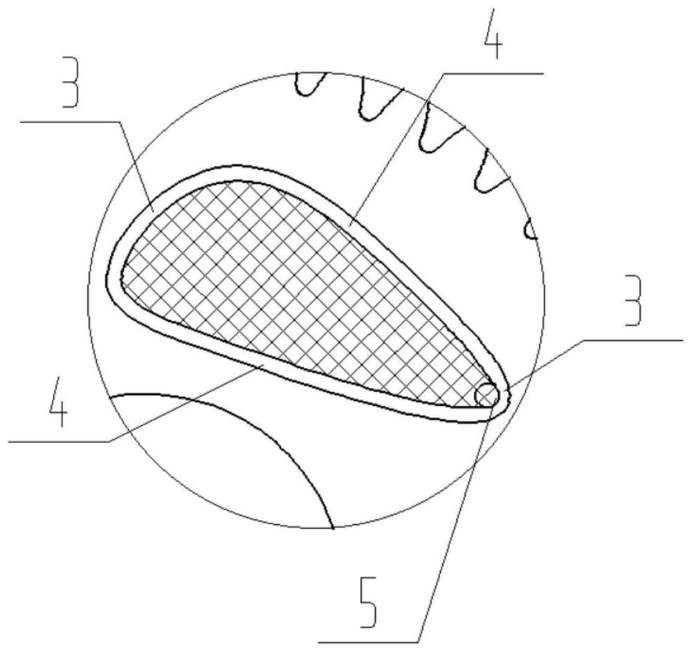
[0034] Such as Figure 1-Figure 7 As shown, the first aspect of the present application discloses a gear lubrication structure, including:

[0035] The oil inlet hole 1 is opened on the same side of the gear ...


PUM


Abstract

The invention relates to the technical field of gearboxes, in particular to a gear lubricating structure, a gear and a gearbox. The gear lubricating structure comprises an oil inlet hole, an oil inletpath and an oil outlet path, wherein the oil inlet hole is formed in the same side of a gear shaft hole, and the hole wall of the oil inlet hole is arranged to be in a streamline shape formed by splicing an arc section and a straight line section; the oil inlet path communicates with the arc section; and one end of the oil outlet path communicates with the oil inlet path, and the other end of theoil outlet path communicates with the gear tooth end. As shown in figure 1, due to the fact that the size of the oil inlet hole is large, the oil outlet amount on the gear is increased on the premisethat the amount of lubricating oil in the gearbox is not changed, moreover, when the gear rotates anticlockwise, the lubricating oil enters the oil inlet path after being accelerated by the straightline section and the arc section in sequence under the action of centrifugal force, by means of the design, the oil inlet speed can be increased, then the oil outlet speed is increased, the flowing speed of the lubricating oil is increased, the heat dissipation effect on the gears is improved, stable meshing between the gears is guaranteed, and the service life of the gear is prolonged.

Description

technical field [0001] The invention relates to the technical field of gearboxes, in particular to a gear lubricating structure, a gear and a gearbox. Background technique [0002] The transmission of the gear mainly depends on the relative occlusion of the tooth surface of the gear to carry out movement and transmission, so that the gear will produce some friction and wear during the movement process. If you want to ensure its normal movement, you need to add lubricating oil to the tooth surface for lubrication. [0003] However, the existing lubricating method has a poor lubricating effect due to the limited oil output, and because the lubricating oil flows slowly, the heat dissipation effect of the gear is poor, which directly shortens the service life of the gear. Contents of the invention [0004] The purpose of the present application is to provide a gear lubricating structure, a gear and a gearbox to solve the problem of poor gear lubricating and heat dissipation ef...

Claims


Application Information

Patent Timeline
Patent Type & Authority Applications(China)
IPC IPC(8): F16H55/17F16H57/04
CPCF16H55/17F16H57/0404F16H57/043F16H57/0431
Inventor 庞晓宇杨晓琴高尤坤张静蓝强唐志伟
Owner GREE ELECTRIC APPLIANCES INC
Why Eureka
Try Eureka