
Steel ball locking quick connector

A steel ball and fast technology, applied in mechanical equipment, couplings, etc., can solve the problems of complex overall joint structure, inconvenient assembly operation, limited operation space, etc., to achieve simple and easy operation, precise and fast docking, The effect of smooth internal circulation

Inactive Publication Date: 2020-12-25
SHANDONG INST OF AEROSPACE ELECTRONICS TECH
View PDF10 Cites 10 Cited by
  • Summary
  • Abstract
  • Description
  • Claims
  • Application Information

AI Technical Summary

Problems solved by technology

The overall structure of the above-mentioned joint is too complicated, and the space available for operation is relatively limited during assembly, which makes the assembly operation inconvenient; in addition, when performing maintenance on springs and other components in the later stage, it is necessary to disassemble the button, that is, the locking part and the lock buckle. Low efficiency, not suitable for field operation

Method used


Image

  • Steel ball locking quick connector
  • Steel ball locking quick connector
  • Steel ball locking quick connector

Examples


Embodiment 1

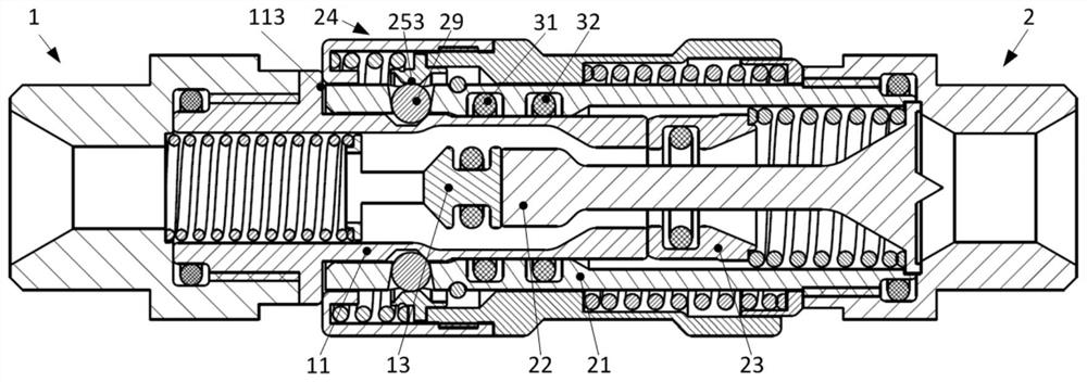
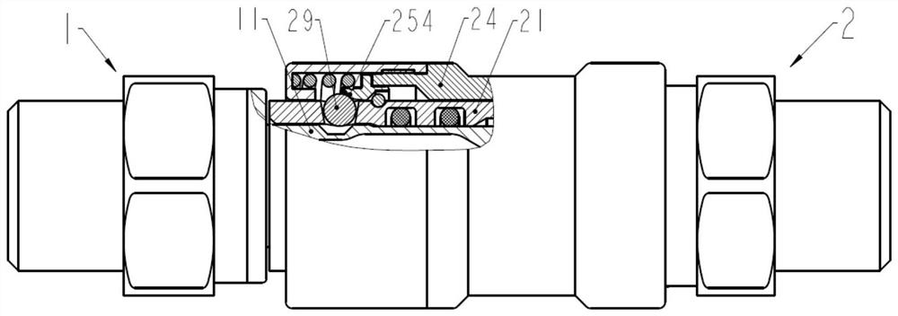
[0039] Example 1, such as Figure 1 to Figure 3 As shown, the present application proposes a new type of steel ball locking quick joint, which includes a male joint 1 and a female joint 2 . specifically,

[0040] The male joint 1 has a male end front housing 11 and a male end rear housing 12 connected by internal and external threads, and a sealing member for sealing is also provided at the thread end; the male end front housing 11 and the male end rear housing The inner cavity of the housing 12 is connected to form a first channel that runs through the front and rear ends of the integral male connector 1;

[0041] In the inner cavity of the front housing 11 of the male end, a male valve core 13, a valve core elastic member 14 and a male end seal 15 are arranged; Between the cores 13, under the elastic support of the valve core elastic member 14, the valve core 13 can reciprocate in a linear motion in the first channel; the male end seal 15 provides self-sealing at the front...

Embodiment 2

[0050] Example 2, such as Figure 4 As shown, the groove 111 outside the front housing 11 of the male connector can have a cross-sectional shape of trapezoidal, semi-oblong or elliptical;

[0051] The inner cavity of the housing 11 in front of the male joint has at least one set of enlarged flow chambers 112 to correspondingly expand the cross-sectional area of ​​the first channel and reduce the flow resistance.

[0052] Other structures are the same as those in Embodiment 1, and will not be repeated here.

Embodiment 3

[0053] Example 3, such as Figure 5 As shown, the valve core 13 is provided with a valve core limit support 131 for supporting the valve core elastic member 14 at its end, and the valve core limit support 131 can be an inner support or an outer support structure.

[0054] A trapezoidal hollow structure 132 is provided through the pipe wall of the valve core 13 to provide good guidance and flow area for fluid flow.

[0055] Other structures are the same as those in Embodiment 1, and will not be repeated here.


PUM


Abstract

The invention discloses a steel ball locking quick connector. A positioning mode of steel ball quick locking is adopted in a fluid pipeline connecting device, so that precise and quick butt joint is achieved on the premise that a male connector and a female connector are sealed correspondingly, fluid circulates inside a pipeline set between butt joint structures effectively, the design purposes ofsimplifying butt joint and unlocking operation, eradicating fluid overflowing and improving the field operation efficiency are achieved, a male end valve element and a valve element elastic piece arearranged in an inner cavity of a male end front shell, the valve element elastic piece is arranged between the inner wall of the rear end of the male end front shell and the male end valve element, under the elastic support of the valve element elastic piece, the valve element does reciprocating rectilinear motion in a first channel formed in an inner cavity of the male connector, a groove is formed in the outer part of the male end front shell, a valve element sleeve, a core shaft and the valve element sleeve elastic piece are arranged in an inner cavity of a female end front shell, and under the elastic support of the valve element sleeve elastic piece, the valve element sleeve does reciprocating rectilinear motion in a second channel formed in an inner cavity of the female connector.

Description

technical field [0001] The invention relates to a novel steel ball locking type quick connector, which belongs to the technical field of fluid pipeline connection. Background technique [0002] With the rapid development of microelectronics technology and chip technology and the emergence of new chip materials, electronic components tend to be high-density and high-integrated, and the heat flux rises rapidly, while the reliability of components is very sensitive to temperature, requiring efficient and reliable Cooling technology provides technical support. At the same time, the heat dissipation problem of equipment is becoming more and more prominent. Because of its efficient heat dissipation performance, liquid cooling technology has become one of the preferred solutions for cooling systems and has been widely used in aerospace, electronics, ships, communications and other fields. As an important component of the liquid cooling system, the quick connector is used to realiz...

Claims


Application Information

Patent Timeline
Patent Type & Authority Applications(China)
IPC IPC(8): F16L37/23F16L37/32
CPCF16L37/23F16L37/32
Inventor 张龙王文正高青徐勤成倪森夏辉
Owner SHANDONG INST OF AEROSPACE ELECTRONICS TECH
Learn More