
Air conditioner and control method thereof

A control method and technology for air conditioners, applied in air conditioning systems, heating methods, space heating and ventilation, etc., can solve problems such as increasing energy consumption, human injury, and increasing the risk of ultraviolet leakage, so as to reduce energy consumption and improve usage. safe effect

Inactive Publication Date: 2020-12-25
HISENSE (SHANDONG) AIR CONDITIONING CO LTD
View PDF6 Cites 0 Cited by
  • Summary
  • Abstract
  • Description
  • Claims
  • Application Information

AI Technical Summary

Problems solved by technology

However, multiple UV lamps not only increase energy consumption, occupy too much space in the indoor unit of the air conditioner, but also increase the risk of ultraviolet light leakage
For the purpose of aesthetics, display effect optimization, and large air output, most air-conditioning indoor units use plastic panels with high light transmittance, light weight, and large air outlets. Therefore, high-power UV lamps will cause ultraviolet rays It leaks out from the gaps in the panel, the air outlet and the structure of the indoor unit, causing harm to the human body.

Method used


Image

  • Air conditioner and control method thereof
  • Air conditioner and control method thereof
  • Air conditioner and control method thereof

Examples


Embodiment 1

[0036] Embodiment 1: a kind of air conditioner.

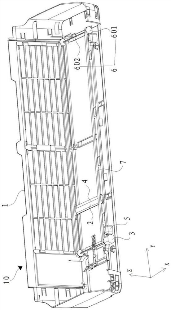
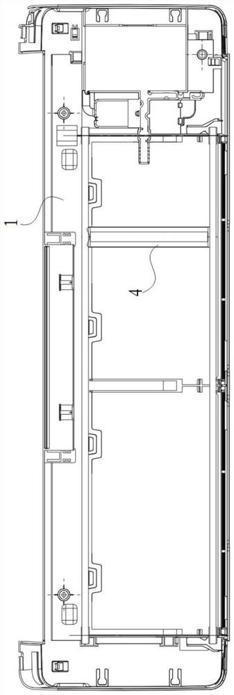
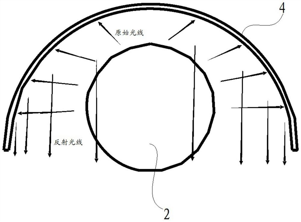
[0037] Such as figure 1 , figure 2 As shown, an air conditioner in a preferred embodiment of the embodiment of the present invention includes: an indoor unit 10, a UV lamp 2 and a driving device 3; the indoor unit 10 includes a body frame 1 and a condenser, and the condenser is installed on the The body frame 1, and the UV lamp is parallel to the surface of the condenser; the UV lamp 2 is slidably installed on the body frame 1; the power output end of the driving device 3 is connected to the UV lamp 2, the driving device 3 drives the UV lamp 2 to slide on the body frame 1 in a direction parallel to the condenser, so that the light emitted by the UV lamp 2 irradiates the surface of the condenser. established as figure 1 In the space Cartesian coordinate system shown, the positive direction of the Y axis is the positive sliding direction of the UV lamp, and the reverse direction of the Y axis is the reverse sliding direction ...

Embodiment 2

[0046] Embodiment 2: a control method of an air conditioner.

[0047] Such as Figure 4 As shown, based on the air conditioner described in Embodiment 1, the control method includes: the air conditioner is in the sterilization mode, the driving device 3 drives the UV lamp 2 to slide on the body frame 1, and the UV lamp 2 emits light to irradiate condensation The device is sterilized.

[0048] Preferably, the air conditioner is in a sterilization mode, and it is detected whether the air conditioner is in a running state;

[0049] When it is detected that the air conditioner is in the running state, the driving device 3 drives the UV lamp 2 to slide at a preset speed A, and the UV lamp 2 emits light to illuminate the condenser, and the preset speed A is realized by controlling the speed of the driving device;

[0050] When it is detected that the air conditioner is not running, the driving device 3 drives the UV lamp 2 to slide at a preset speed B, and the UV lamp 2 emits ligh...


PUM


Abstract

The invention relates to the technical field of air conditioners, and discloses an air conditioner and a control method thereof. The air conditioner comprises an indoor unit, a UV lamp and a driving device, wherein the indoor unit comprises a unit body frame and a condenser; the condenser is mounted in the unit body frame; the UV lamp is mounted on the unit body frame in a sliding manner; the power output end of the driving device is connected with the UV lamp; and the driving device drives the UV lamp to slide on the unit body frame in the direction parallel to the condenser, so that light emitted by the UV lamp irradiates the surface of the condenser. The UV lamp is used for comprehensively irradiating and sterilizing the condenser of the indoor unit, so that deep purification of the condenser is achieved.

Description

technical field [0001] The invention relates to the technical field of air conditioners, in particular to an air conditioner and a control method thereof. Background technique [0002] At present, the air conditioners in the industry have not yet used UV lamps on a large scale to sterilize air conditioners and purify the air. The reasons are as follows: [0003] On the one hand, it is impossible to carry out deep-level and all-round sterilization of the condenser. In household air conditioners, the places where bacteria are easy to breed are mainly condensers and filters. Due to the small fin spacing of the condenser, it is easy to gather water droplets during operation, etc., the bacterial growth of the condenser is very serious. However, the traditional UV lamp installation method is affected by the internal structure of the air conditioner, and the installation position is relatively limited. As a result, it can only irradiate one side of the condenser and cannot achie...

Claims


Application Information

Patent Timeline
IPC IPC(8): F24F1/0063F24F1/0071F24F11/64F24F11/72F24F13/30
CPCF24F13/30F24F11/64F24F11/72F24F1/0063F24F1/0071
Inventor 李承锟段然张明磊
Owner HISENSE (SHANDONG) AIR CONDITIONING CO LTD
Learn More