Power monitoring equipment with protection device

A technology for power monitoring and protection devices, which is applied to the structural parts of electrical equipment, measuring devices, and housings of measuring devices, etc. It can solve the problems of inconvenient maintenance and cleaning of power monitoring devices, and reduce the convenience of maintenance.

Inactive Publication Date: 2020-12-25
黄美婷
View PDF8 Cites 0 Cited by
  • Summary
  • Abstract
  • Description
  • Claims
  • Application Information

AI Technical Summary

Problems solved by technology

[0004] The purpose of the present invention is to provide a power monitoring device with a protection device to solve the problem that the power monitoring system with a protection device in the prior art cannot protect the power monitoring device when used in the above-mentioned background technology. It can drive the power monitoring device to rotate and fix, which makes it inconvenient to overhaul and clean the power monitoring device, reducing the convenience of maintenance

Method used


Image

  • Power monitoring equipment with protection device
  • Power monitoring equipment with protection device
  • Power monitoring equipment with protection device

Examples


Embodiment 1

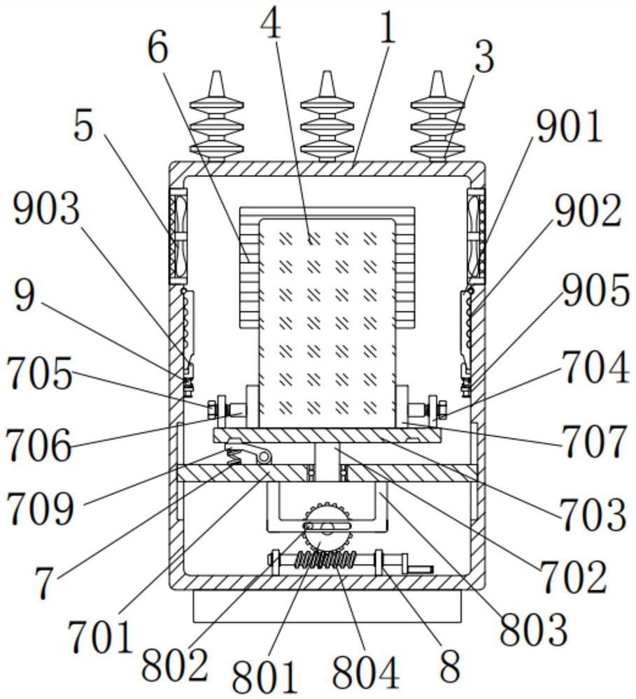
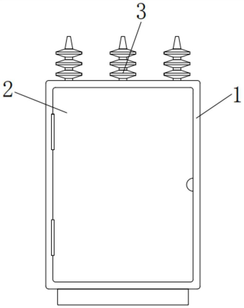
[0035] A power monitoring device with a protection device, including a housing 1, the front of the housing 1 is rotatably connected with a cover plate 2, and the top of the housing 1 is installed with a lightning arrester 3, which can play the role of lightning protection, and the inner wall of the housing 1 is equipped with a power monitoring Device 4, fans 5 are embedded in the left and right ends of the casing 1, and the fans 5 are used to cool and dissipate the power monitoring device 4. The rear end of the casing 1 is equipped with an exhaust window 6, and the power monitoring device 4 is provided below. There is a fixed assembly 7, and the fixed assembly 7 includes a horizontal plate 701, a vertical bar 702, a supporting plate 703, a support plate 704, a bolt 705, a sleeve 706, a splint 707, a slot 708, a clamping rod 709 and a first spring 710, and the horizontal plate The outer wall of 701 fits with the lower part of the inner wall of the housing 1. The top of the horiz...

Embodiment 2

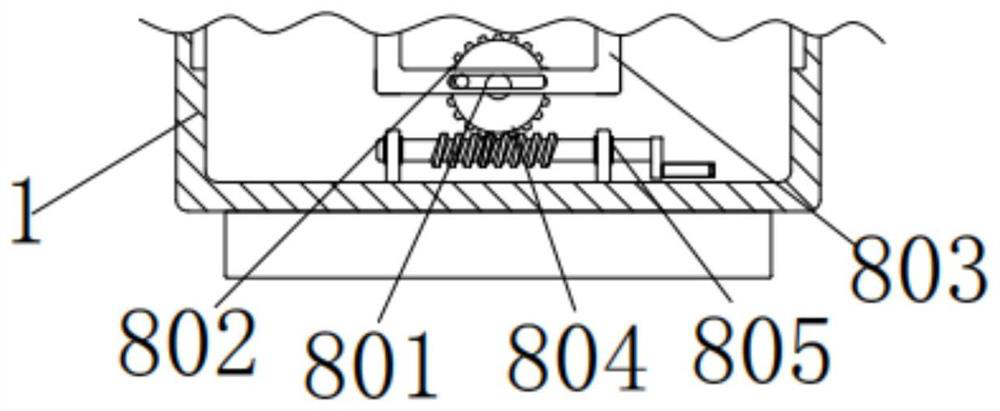
[0037] As an option, see figure 1 and 2, a power monitoring system with a protection device, a lifting assembly 8 is provided below the horizontal plate 701, and the lifting assembly 8 includes a worm wheel 801, a round rod 802, a curved bracket 803, a worm screw 804 and a bracket 805, the back of the worm wheel 801 and the shell 1 Rotating connection under the inner wall of the worm wheel 801, the front left side of the worm wheel 801 is fixedly connected with a round rod 802, the outer wall of the round rod 802 is matched with the preset slide rail under the front of the curved bracket 803, and the round rod 802 can rotate through the curved bracket. The frame 803 drives the horizontal plate 701 to move up and down, the top of the curved bracket 803 is fixedly connected with the bottom of the horizontal plate 701, the bottom of the worm wheel 801 is meshed with a worm 804, and the right end of the worm 804 is fixedly connected with a handle, which is convenient for adjusting...

Embodiment 3

[0040] As an option, see figure 1 and 6 , a power monitoring system with a protection device, the inner wall of the housing 1 is provided with clamping components 9 on the left and right sides, and the clamping components 9 include a rubber plate 901, a limit groove 902, an angular clamping plate 903, a T-shaped sliding bar 904, a square The collar 905 and the second spring 906, the tops of the two rubber plates 901 are rotatably connected with the left and right sides of the inner wall of the housing 1, and the outer ends of the rubber plates 901 are processed with limiting grooves 902, and the limiting grooves 902 are longitudinally equidistantly distributed, so that The design is convenient to limit the position of the wire. The inner bottom of the rubber plate 901 is clamped with an angled clamping plate 903, and the contact surface between the rubber plate 901 and the angled clamping plate 903 is an inclined plane, so that the design can make the rubber plate 901 resist a...


PUM


Abstract

The invention discloses power monitoring equipment with a protection device. The equipment comprises a housing, wherein the front surface of the housing is rotationally connected to a cover plate, thetop of the housing is provided with a lightning arrester, the inner wall of the housing is provided with the power monitoring device, and a fixed assembly is arranged below the power monitoring device. According to the power monitoring system with the protection device, through threaded connection between a bolt and a sleeve, the bolt can be rotated to drive a clamping plate to slide inwards, sothat the power monitoring device can is fixed in an abutting manner conveniently, the power monitoring device can be protected through the shell, the power monitoring device can be overhauled and cleaned conveniently, through the clearance fit between a T-shaped sliding rod and a square lantern ring and the clamping connection between a rubber plate and an angular clamping plate, under the actionof a second spring, wires of the power monitoring device can be sequentially embedded into limiting grooves to be clamped and fixed, so that the wire arrangement effect on the power monitoring deviceis achieved, and the situation that the disassembly, assembly and maintenance efficiency are affected due to disorder of the wires is avoided.

Description

technical field [0001] The invention relates to the technical field of a power monitoring system with a protection device, in particular to a power monitoring device with a protection device. Background technique [0002] At present, electric power equipment is widely used in various places, and regular maintenance is required during its use. Power monitoring equipment can effectively monitor and repair power equipment, but existing power monitoring equipment generally does not have protection functions. [0003] When the power monitoring system with protection device in the prior art is in use, it cannot protect the power monitoring device, and cannot drive the power monitoring device to rotate and fix it, which makes it inconvenient to overhaul and clean the power monitoring device, reducing maintenance Convenience, it cannot play the role of air cooling and heat dissipation for the power monitoring device, thereby shortening its service life. Basically, it is impossible ...

Claims


Application Information

Patent Timeline
IPC IPC(8): G01D11/24G01D11/16H05K7/20
CPCG01D11/24G01D11/16H05K7/20172
Inventor 黄美婷
Owner 黄美婷
Why Eureka
Try Eureka