Membrane cleaning device and membrane cleaning method

A technology for membrane cleaning and membrane separation, applied in chemical instruments and methods, membrane technology, semi-permeable membrane separation, etc., can solve problems such as reduced filtration performance and clogging, and achieve the effects of reducing costs and shortening processing time

Active Publication Date: 2020-12-25
MITSUBISHI ELECTRIC CORP
View PDF10 Cites 0 Cited by
  • Summary
  • Abstract
  • Description
  • Claims
  • Application Information

AI Technical Summary

Problems solved by technology

As for the separation membrane of MBR, with continuous use, fouling substances adhere to the surface or pores, and clogging occurs, so the filtration performance gradually decreases

Method used


Image

  • Membrane cleaning device and membrane cleaning method
  • Membrane cleaning device and membrane cleaning method
  • Membrane cleaning device and membrane cleaning method

Examples


Embodiment approach 1

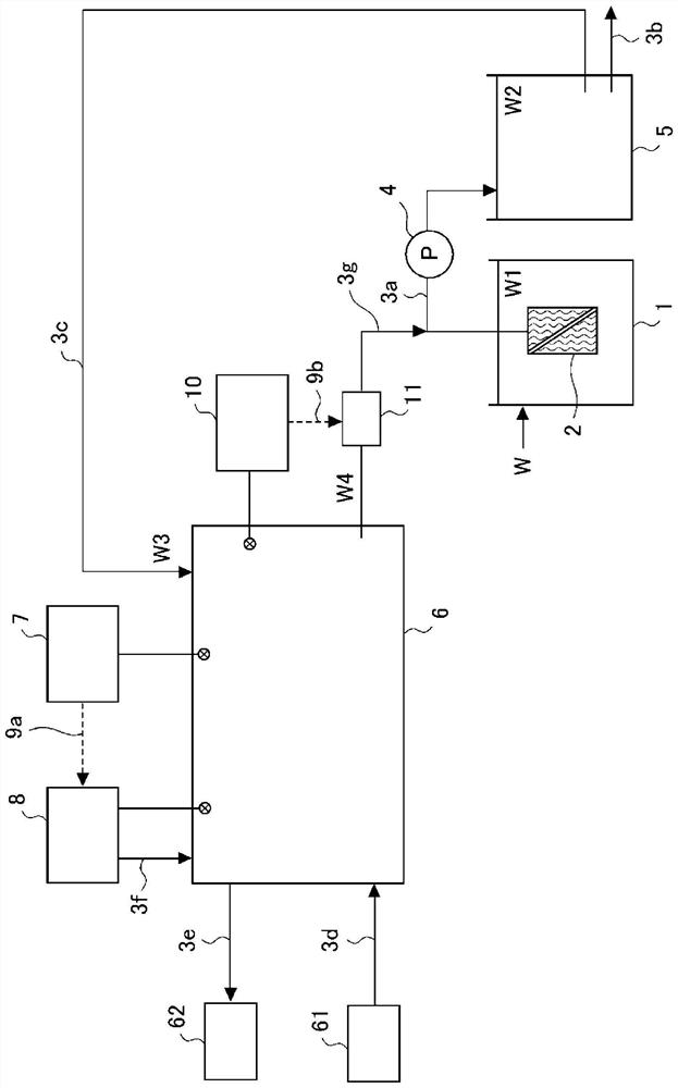
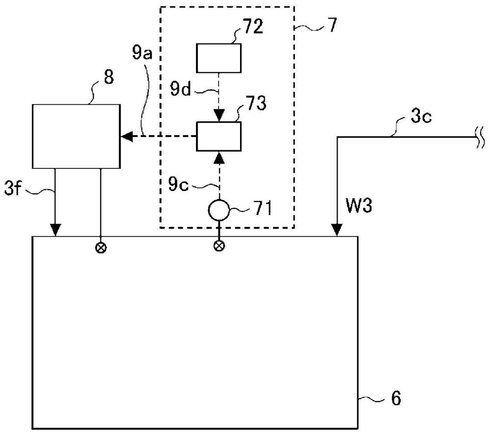
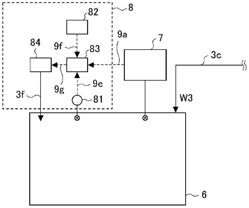
[0035]Hereinafter, the membrane cleaning device and membrane cleaning method according to the first embodiment of the present application will be described based on the drawings.figure 1 The overall configuration of the membrane cleaning device according to Embodiment 1 is shown. In addition,figure 2 ,image 3 andFigure 4 The configurations of the process transition determination unit, the pH adjustment unit, and the water supply start determination unit of the membrane cleaning device according to Embodiment 1 are shown respectively. In each figure, the same reference numerals are given to the same and corresponding parts.

[0036]For the overall configuration of the membrane cleaning device according to Embodiment 1, usefigure 1 Let's briefly explain. The membrane cleaning device, for example, in a water treatment system using MBR, cleans the separation membrane 2 that separates the water to be treated W1 containing activated sludge into activated sludge and treated water W2. It shoul...

Embodiment approach 2

[0077]Picture 8 Shows the overall configuration of the membrane cleaning device according to Embodiment 2 of the present application,Picture 9 The configuration of the process transition judging unit of the membrane cleaning device according to Embodiment 2 is shown. Regarding the membrane cleaning device according to the second embodiment, only the configuration of the process transition judging unit is different from the membrane cleaning device according to the above-mentioned first embodiment, and the other configurations are the same, so the description is omitted here.

[0078]The membrane cleaning apparatus according to Embodiment 2 includes a process transition judging unit 7A. As far as the process transfer judgment unit 7A is concerned,Picture 9 As shown in FIG. 1, an organic matter sensor 74, an ozone gas sensor 75, a memory (third memory) 72A, and a comparison unit (third comparison unit) 73A are provided. The organic matter sensor 74 and the comparison unit 73A, the ozone ...

Embodiment approach 3

[0088]Picture 11 The overall configuration of the membrane cleaning device according to Embodiment 3 of the present application is shown. Regarding the membrane cleaning device according to the third embodiment, only the configuration of the process transition judging unit is different from the membrane cleaning device according to the above-mentioned first embodiment, and the other configurations are the same, so the description is omitted here.

[0089]The membrane cleaning apparatus according to Embodiment 3 includes a process transition judging unit 7B. With regard to the process transition judging unit 7B, such asPicture 11 As shown in the figure, it includes a dissolved ozone sensor 76, an ozone gas sensor 75, a memory (fourth memory) 72B, and a comparison unit (fourth comparison unit) 73B. The dissolved ozone sensor 76 and the comparison unit 73B, the ozone gas sensor 75 and the comparison unit 73B, the memory 72B and the comparison unit 73B, and the comparison unit 73B and the ...


PUM


Abstract

This membrane cleaning device generates ozone water as a result of carrying out, using treated water that has been filtration-treated by a membrane bioreactor (MBR) separation membrane (2) as dissolution water, the following steps: a first step for dissolving ozone gas in the dissolution water under neutral or alkaline conditions; and a second step for dissolving ozone gas in the dissolution waterunder acidic conditions. At such time, a transition from the first step to the second step is assessed on the basis of the organic matter concentration of the dissolution water, and the start of ozone water pumping to the separation membrane (2) is assessed on the basis of the dissolved ozone concentration of the dissolution water. This makes it possible to optimize the treatment times of the first step and the second step even if MBR operating conditions cause fluctuations in the organic matter concentration of the dissolution water. Due to this configuration, ozone water can be generated efficiently, and the costs of generating ozone water can be reduced.

Description

Technical field[0001]The present application relates to a membrane cleaning device and a membrane cleaning method for cleaning a separation membrane that filters water to be treated with ozone water.Background technique[0002]As a treatment method for wastewater containing organic matter (hereinafter referred to as water to be treated), membrane separation in which the organic matter in the water to be treated is decomposed by activated sludge containing microorganisms, and solid-liquid separation is performed by filtration treatment using a separation membrane is known Activated sludge method (Membrane Bio Reactor: hereinafter referred to as MBR). With regard to MBR separation membranes, with continuous use, contaminants adhere to the surface or pores, causing clogging, so the filtration performance gradually decreases. Therefore, in the membrane separation tank for filtration treatment, a membrane cleaning device that cleans the separation membrane with ozone water is installed in ...

Claims


Application Information

Patent Timeline
Patent Type & Authority Applications(China)
IPC IPC(8): B01D65/06C02F1/44C02F1/78C02F3/12
CPCC02F1/44C02F1/78Y02W10/10B01D2321/40B01D2321/162B01D2321/168B01D65/022C02F3/1268C02F1/66C02F2303/16C02F2209/23C02F2209/06C02F2201/782B01D2321/44B01D65/02C02F3/1273B01D2321/12C02F1/008C02F2209/10
Inventor 林佳史今村英二野田清治
Owner MITSUBISHI ELECTRIC CORP
Why Eureka
Try Eureka