Steam generating system

A technology for generating system and steam, applied in the direction of steam generation, steam generation device, steam generation method, etc., can solve the problems such as the inability to ensure the steam in the ship and the inability to use the exhaust gas economizer to recover energy, etc.

Inactive Publication Date: 2018-04-06
TSUNEISHI SHIPBUILDING
View PDF3 Cites 0 Cited by
  • Summary
  • Abstract
  • Description
  • Claims
  • Application Information

AI Technical Summary

Problems solved by technology

[0008] However, when the temperature of the exhaust gas decreases due to the continuous improvement of the thermal efficiency of the main engine, there is a problem that sufficient energy cannot be recovered by the exhaust gas economizer, and even if the exhaust gas economizer of the generator is used together, the exhaust gas cannot be guaranteed. Inboard vapors in common voyages

Method used


Image

  • Steam generating system
  • Steam generating system
  • Steam generating system

Examples


Embodiment Construction

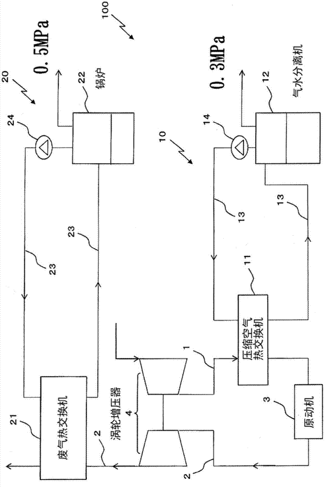
[0028] Next, refer to figure 1 , the steam generating system according to the embodiment of the present invention will be described. figure 1 It is a configuration diagram of the steam generating system 100 according to the embodiment of the present invention. The steam generating system 100 is used to generate steam on board a ship, and includes a scavenging side steam generating unit 10 and an exhaust gas side steam generating unit 20 using waste heat from a prime mover 3 (engine or generator). Furthermore, the steam used in the ship is divided into a low-pressure system (0.3 MPa in this embodiment) and a high-pressure system (0.5 MPa in this embodiment), so that low-pressure steam is generated in the scavenging side steam generation unit 10, and the exhaust gas The side steam generator 20 generates high-pressure steam. The medium used in this embodiment is water.

[0029] In addition, the numerical value of low-pressure steam and high-pressure steam can be changed suitab...


PUM


Abstract

The invention provides a steam generating system that can efficiently use heat of the scavenging gas to generate steam, and the heat of the scavenging gas can be converted to steam without leaving waste heat of a prime mover. The steam generating system includes a scavenging side steam generating unit (10) and an exhaust gas side steam generating unit (20). The scavenging side steam generating unit (10) has a compressed air heat exchanger (11), a gas-water separator (12) generating steam from a first medium, a first circulation line (13) circulating the first medium, and a first pump (14) arranged on the first circulation line (13). The exhaust gas side steam generating unit (20) has an exhaust heat exchanger (21), a boiler (22) that generates steam from a second medium, a second circulation line (23) circulating the second medium, and a second pump (24) that is disposed on the second circulation line (23). The scavenging side steam generating unit (10) generates low-pressure steam, and the exhaust gas side steam generating unit (20) generates high-pressure steam.

Description

technical field [0001] The present invention relates to steam generating systems. Background technique [0002] Conventionally, as a method of generating steam inboard during common voyages of ships, exhaust gas economizers using exhaust heat from main engines and / or generators, and scavenging heat from compressed air serving as main engines are known. A feed water heater that heats feed water to a boiler. The exhaust gas of the main engine is relatively high temperature (such as 200-250°C), and the exhaust gas economizer can be used to generate high-temperature and high-pressure steam. In contrast, the heat of the scavenging air is relatively low (such as 170°C), and only the scavenging gas is used The heat cannot generate high-temperature and high-pressure steam, so it stays in the application of heating the water supply to the boiler. [0003] On the other hand, Patent Document 1 describes an invention of a boiler system using waste heat from a prime mover. A boiler uni...

Claims


Application Information

Patent Timeline
Patent Type & Authority Applications(China)
IPC IPC(8): F22B1/18F22B33/18
CPCF22B1/1892F22B33/18Y02E20/30F22B1/1807F22B33/14F22B37/26
Inventor 柴田宪一山本弘行冈崎健太郎
Owner TSUNEISHI SHIPBUILDING
Why Eureka
Try Eureka