Strip steel coiling system, high-strength steel coiling method and high-strength steel production line

A technology for high-strength steel and strip steel, applied in the field of high-strength steel production lines, can solve the problems of difficult bundling of strip steel, high resilience, and accidents, so as to improve the coiling effect, reduce the rebound force, and avoid bulging.

Pending Publication Date: 2020-12-29
WISDRI ENG & RES INC LTD
View PDF2 Cites 3 Cited by
  • Summary
  • Abstract
  • Description
  • Claims
  • Application Information

AI Technical Summary

Problems solved by technology

[0003] 1) Since the high-strength steel is difficult to bend, head tilting or bowing will cause great damage to the threading guide plate, especially when entering the jaws, it is difficult to enter automatically;
[0004] 2) When the steel strip clamped by the jaws is just started to be coiled, because the full tension cannot be established, generally only 50% tension can be used for coiling. At this time, it is difficult for the high-strength steel to adhere to the reel, especially near the jaws. It will bulge a bag, which will cause the steel coil to become a convex circle and cannot be a perfect circle, resulting in a reduction in the tension control accuracy of coiling;
[0005] 3) When coiling the last lap, due to the cutting of the strip tail, the tail of the strip loses the back tension, and the high-strength rebound will cause the last few laps to be uncoiled;
[0006] 4) When the coil is unloaded after coiling, due to the strong rebound force of the high-strength steel, when the jaws are opened, the springback of the strip will be stuck in the jaws and it is difficult to unload the coil;
[0007] 5) The resilience of the last lap of the steel coil is very large, especially the high-strength steel of the thick plate, which causes great difficulty in bundling the strip steel. Loose rolls may cause accidents

Method used


Image

  • Strip steel coiling system, high-strength steel coiling method and high-strength steel production line
  • Strip steel coiling system, high-strength steel coiling method and high-strength steel production line
  • Strip steel coiling system, high-strength steel coiling method and high-strength steel production line

Examples


Embodiment 1

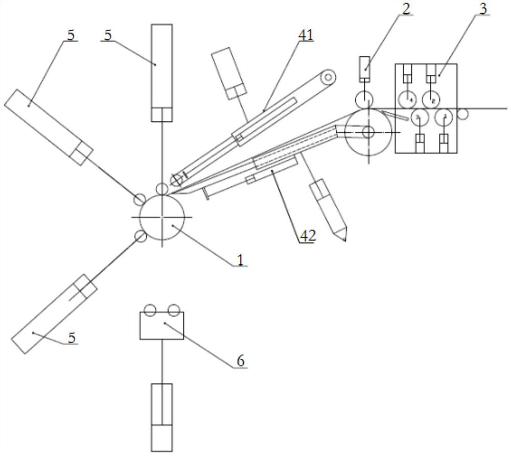
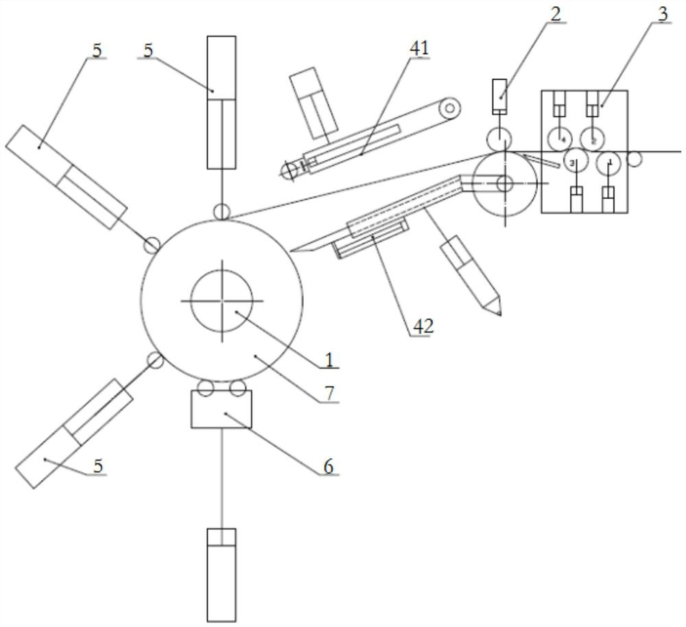
[0033] Such as figure 1 with figure 2 , the embodiment of the present invention provides a strip coiling system, including a coiler, a steering pinch roller 2 and an unloading car 6, the steering pinch roller 2 is connected with the coiler through a threading guide plate, so The incoming side of the steering pinch roller 2 is provided with a bending machine 3, and at least one auxiliary pressing roller 5 is arranged around the reel 1 of the coiler, and the axial direction of the auxiliary pressing roller 5 is in line with the reel. 1 is parallel to the axial direction, and the auxiliary pressing roller 5 is configured with a driving unit of the auxiliary pressing roller 5 so as to have a working position in rolling contact with the steel coil 7 and a standby position away from the steel coil 7 .

[0034] The coiler, the steering pinch roller 2 and the coil unloading car 6 are all conventional equipment in the field, and the specific structure will not be repeated here.

[0...

Embodiment 2

[0043] The embodiment of the present invention provides a winding jaw, which can be used on the reel 1 in the first embodiment above as the reel 1 jaw.

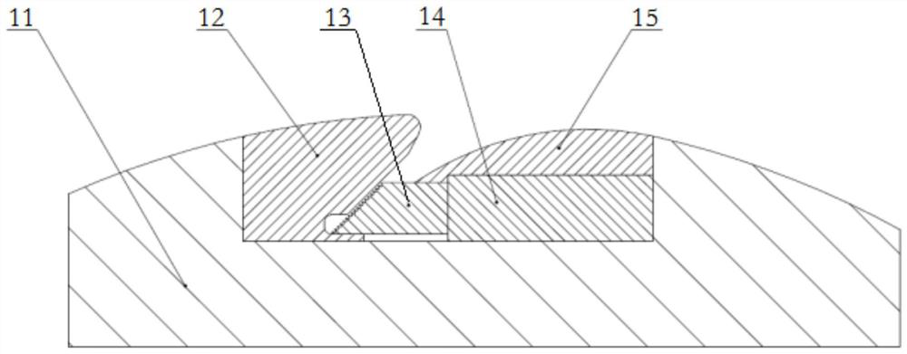
[0044] Such as image 3 , the jaws include a sector plate 11, a groove is formed on the sector plate 11, a fixed jaw plate 12 is provided on one side of the groove wall and a movable jaw plate is provided in the groove 13 and a jaw drive unit 14 for driving the movable jaw plate 13 close to or away from the fixed jaw plate 12, the other side of the groove is provided with an outlet guide plate 15, and the fixed jaw plate 12 is provided with an outlet guide plate 15. The jaw steel surface of the jaw plate 12 is inclined and its outer end is positioned at the side of its inner end close to the outlet guide plate 15. The space enclosed by the mouth plate 12 gradually expands from inside to outside.

[0045] Wherein, preferably, the above-mentioned jaw driving unit 14 is a hydraulic cylinder, adopting a hydraulic jaw can increa...

Embodiment 3

[0052] An embodiment of the present invention provides a high-strength steel coiling method, using the strip coiling system provided in the first embodiment above to coil the high-strength steel strip, and the method includes:

[0053] a. If figure 1 In the early stage of coiling, the bending machine 3 is used to straighten the strip steel, so as to prevent the strip steel from warping or bowing to damage the strip guide plate, and to make the strip steel, especially the high-strength steel, enter the clamp of the reel 1 smoothly and accurately. Mouth; The specific straightening operation has been mentioned in the above-mentioned embodiment one, and will not be repeated here.

[0054] The steel strip is guided to the reel 1 by the turning pinch roller 2 and the threading guide plate, which is a conventional operation in the art, and will not be described in detail here;

[0055] The jaws of the reel 1 clamp the strip steel, and the diameter of the reel 1 expands to establish ...


PUM


Abstract

The invention relates to a strip steel coiling system, a high-strength steel coiling method based on the strip steel coiling system and a high-strength steel production line adopting the strip steel coiling system. The coiling system comprises a coiling machine, a steering pinch roller and a coil unloading vehicle. The steering pinch roller is connected with the coiling machine through a strip penetrating guide plate, and a bending machine is arranged on the feeding side of the steering pinch roller; and at least one auxiliary pressing roller is arranged around a winding drum of the coiling machine, the axial directions of the auxiliary pressing rollers are parallel to the axial direction of the winding drum, and the auxiliary pressing rollers are provided with auxiliary pressing roller driving units so as to have working positions in rolling contact with a steel coil and standby positions away from the steel coil. The bending machine can straighten strip steel at the initial stage ofcoiling to prevent the strip penetrating guide plate from being damaged, the strip steel is made to generate plastic deformation at the final stage of coiling, rear tension can be provided for coiling, and bounce of the outer-ring strip steel can be reduced; and the auxiliary pressing rollers can enable the strip steel to be attached to the winding drum/steel coil in the coiling process, the winding effect of the strip steel is improved, and the problem that when high-strength steel and other steel types are wound, bumps exist near a jaw can be avoided.

Description

technical field [0001] The invention relates to a strip steel coiling system, a high-strength steel coiling method based on the strip steel coiling system and a high-strength steel production line using the strip steel coiling system. Background technique [0002] The high-strength steel market is gradually expanding. In order to increase the production capacity of equipment, the production of high-strength strip steel has gradually expanded from the previous production of single sheets to the direction of continuous production. In order to adapt to flexible and changeable production methods, high-strength strip steel coiling has become a difficult point. The main problems are as follows : [0003] 1) Since the high-strength steel is difficult to bend, head tilting or bowing will cause great damage to the threading guide plate, especially when entering the jaws, it is difficult to enter automatically; [0004] 2) When the steel strip clamped by the jaws is just started to b...

Claims


Application Information

Patent Timeline
Patent Type & Authority Applications(China)
IPC IPC(8): B21C47/06B21C47/34B21C47/26B21C47/32B21C47/24B21D1/02
CPCB21C47/063B21C47/24B21C47/26B21C47/32B21C47/3441B21D1/02
Inventor 马瑞杰廖砚林况群意王鹏波许立雄
Owner WISDRI ENG & RES INC LTD
Why Eureka
Try Eureka