Clamping device for optical lens processing

A clamping device and optical lens technology, applied in the direction of grinding workpiece supports, etc., can solve the problems of inconvenient processing, damage and damage of lens raw materials, etc., and achieve the effect of facilitating processing and avoiding damage

Inactive Publication Date: 2020-12-29
广州图宇科技有限公司
View PDF8 Cites 0 Cited by
  • Summary
  • Abstract
  • Description
  • Claims
  • Application Information

AI Technical Summary

Problems solved by technology

[0002] As we all know, optical lenses are an indispensable tool in scientific experiments, and in the process of its production and processing, in order to ensure the accuracy of scientific experiments, the accuracy of optical lenses in production is also very important, and in its production process Clamping processing is the most important step, but the common lens clamping devices on the market still have the following deficiencies: 1. The force of the clamp is relatively large when clamping the lens, resulting in damage or damage to the raw material of the lens; 2. The traditional clamping device The holding device only has a single clamping function, which cannot realize both horizontal and vertical clamping functions, which makes processing inconvenient; 3. In the traditional working mode, the optical lens needs to be clamped first, and then Go to the machine that can detect eccentricity to perform eccentricity detection. If the detection is unqualified, it needs continuous processing and testing, and the staff needs to run back and forth non-stop, which is very time-consuming and labor-intensive, and the work efficiency is low.

Method used


Image

  • Clamping device for optical lens processing
  • Clamping device for optical lens processing
  • Clamping device for optical lens processing

Examples


Embodiment Construction

[0025] The following will clearly and completely describe the technical solutions in the embodiments of the present invention with reference to the accompanying drawings in the embodiments of the present invention. Obviously, the described embodiments are only some, not all, embodiments of the present invention. Based on the embodiments of the present invention, all other embodiments obtained by persons of ordinary skill in the art without making creative efforts belong to the protection scope of the present invention.

[0026] The embodiment of clamping device for this optical lens processing is as follows:

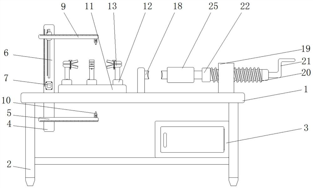
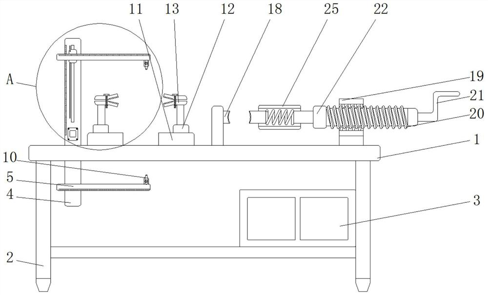
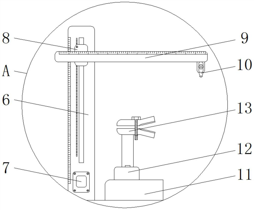
[0027] see Figure 1-7 , including table body 1, legs 2, storage box 3, first installation support 4, first installation support 5, second installation support 6, electronic digital display screen 7, first slider part 8, second installation support 9. Infrared range finder 10, base 11, second slider part 12, adjustable clamp assembly 13, turntable rack 14, adjustment ro...


PUM


Abstract

The invention provides a clamping device for optical lens processing, and relates to the technical field of optical lens processing. The clamping device for optical lens processing comprises a table body, wherein supporting legs are fixedly installed at the bottom of the table body, a storage box is fixedly installed on one side of one supporting leg, a first installation supporting column is fixedly installed at the bottom of the table body, and a first installation support is movably installed on the surface of the first installation supporting column through a sliding groove. According to the clamping device for optical lens processing, through a cooperation clamp part and a fixed clamp part,lenses are vertically clamped, a compression spring has a buffering effect while a user processes the lenses, and damage of a clamp to the lenses is avoided; synchronous movement of an adjustable clamp assembly is achieved through linkage of a rotary disc rack, a flat tooth gear and a tooth chain, so that the lenses of different sizes can be clamped, and the clamping device has a duplex clamping function; and through the structural cooperation between infrared distance meters, whether the lenses are concentric or eccentric can be effectively measured.

Description

technical field [0001] The invention relates to the technical field of optical lens processing, in particular to a clamping device for optical lens processing. Background technique [0002] As we all know, optical lenses are an indispensable tool in scientific experiments, and in the process of its production and processing, in order to ensure the accuracy of scientific experiments, the accuracy of optical lenses in production is also very important, and in its production process Clamping processing is the most important step, but the common lens clamping devices on the market still have the following deficiencies: 1. The force of the clamp is relatively large when clamping the lens, resulting in damage or damage to the raw material of the lens; 2. The traditional clamping device The holding device only has a single clamping function, which cannot realize both horizontal and vertical clamping functions, which makes processing inconvenient; 3. In the traditional working mode,...

Claims


Application Information

Patent Timeline
Patent Type & Authority Applications(China)
IPC IPC(8): B24B41/06
CPCB24B41/06
Inventor 袁承宇
Owner 广州图宇科技有限公司
Why Eureka
Try Eureka