Mold making method of thermal forming plastic suction female mold and female mold

A technology of thermoforming and negative mold, which is applied to the molding method and the field of the female mold of thermoforming blister, which can solve the problems of reducing the service life of the mold, making it difficult to ensure the integrity of the blister, and failing to make reasonable use of negative pressure. Achieve the effect of improving production efficiency

Pending Publication Date: 2020-12-29
北京科技大学天津学院
View PDF2 Cites 2 Cited by
  • Summary
  • Abstract
  • Description
  • Claims
  • Application Information

AI Technical Summary

Problems solved by technology

[0003] 1. Failure to make reasonable use of the negative pressure during vacuum adsorption affects the production efficiency of blister molding;
[0004] 2. The air extraction holes in the cavity are not designed for position layout, which is easy to reduce the molding quality of the finished product;
[0005] 3. The rounding treatment of the sharp corners, corners and edge positions in the cavity of the main body of the mold is not considered, resulting in poor molding quality of the thermoplastic film at the aforementioned positions;
[0006] 4. Failure to set an appropriate demoulding slope for the cavity in the main body of the mold makes it difficult to ensure the integrity of the blister and affects the smooth demoulding of the finished product (product);
[0007] 5. When opening the air extraction hole, the relationship between it and the minimum wall thickness of the mold body is not considered, and the service life of the entire mold is likely to be reduced due to the unreasonable opening position

Method used


Image

  • Mold making method of thermal forming plastic suction female mold and female mold
  • Mold making method of thermal forming plastic suction female mold and female mold
  • Mold making method of thermal forming plastic suction female mold and female mold

Examples


Embodiment 1

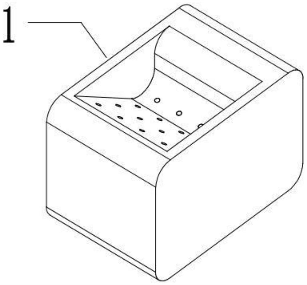
[0077] Such as Figure 1-Figure 9 Shown, a kind of molding method of thermoformed blister female mold comprises the following steps:

[0078] S1, 3D modeling to build the model data of mold body 1;

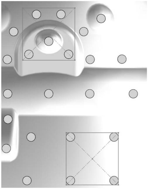
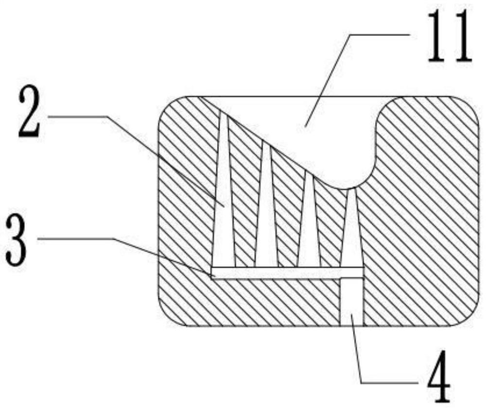
[0079] S2. In the model of the mold main body 1, construct the air extraction channel data formed by connecting multiple groups of air extraction holes 2, series holes 3 and total air outlet holes 4, wherein the air extraction holes 2 penetrate to the cavity 11 of the mold body 1, and the series holes The direction of 3 matches the shape of the bottom wall of the cavity 11, and the series holes 3 start from the total air outlet 4 according to the distance from the air inlet of the air extraction hole 2 to the top plane of the mold body 1, and connect multiple groups in series from far to near. The air extraction hole 2 and the total air outlet hole 4 pass through the main body of the mold 1;

[0080] S3. According to the above construction data, use 3D printing or machining to m...

Embodiment 2

[0110] Such as figure 1 and figure 2 As shown, the difference from Embodiment 1 is that, further, in step S3 of Embodiment 1 above, when using 3D printing to make a female mold,

[0111] 1) For the production of the air extraction hole 2, a draft angle of 0°-5° needs to be produced according to the length of the air extraction hole 2, and the minimum diameter d is greater than 2mm. Specifically, the draft angle of 0°-5° The drawing direction of the degree is the direction of gradually expanding from the bottom wall side of the cavity 11 to the bottom wall side of the mold main body 1;

[0112] 2) The cross-section of the serial hole 3 is set to be an equilateral triangle;

[0113] 3) The minimum wall thickness l of the mold main body 1 is greater than 3mm, and the internal filling rate of the mold main body 1 is 60%-90%, and it should be as compact as possible. Specifically, for a 3D printed female mold, the resistance of the female mold must The heat is not very good, so ...

Embodiment 3

[0115] Such as Figure 3-Figure 6 As shown, the difference from Embodiment 1 is that, further, in step S3 of Embodiment 1 above, the use of machining to make the female mold includes the following steps:

[0116] Step 1. Divide the mold base for the female mold into an upper mold 12 and a lower mold 13 according to the processing position of the serial hole 3 to be processed;

[0117] Step 2. In the upper mold 12, mill the cavity 11 of the mold body 1 according to the model data constructed in the step S1 of the first embodiment, and according to the model data constructed in the step S2 of the first embodiment, in the upper mold 12 Provide air extraction hole 2 on the top, meanwhile, according to the model data constructed in the step S2 of embodiment one, offer serial hole 3 and total air outlet hole 4 on lower mold 13;

[0118] Step 3: Clamp the upper mold 12 and the lower mold 13 processed in step 2 to form a female mold.

[0119] Specifically, the upper mold 12 mainly e...


PUM


Abstract

The invention provides a mold making method of a thermal forming plastic suction female mold and the female mold. The mold making method of the thermal forming plastic suction female mold comprises the following steps that S1, 3D modeling is performed to construct data of a mold main body model; S2, in the mold main body model, air exhaust channel data formed by communicating a plurality of groupsof air exhaust holes, series holes and a main air outlet hole are constructed, the air exhaust holes penetrate into a cavity of a mold main body, the trend of the series holes is matched with the shape of the bottom wall of the cavity, the series holes are sequentially connected with the plurality of groups of air exhaust holes in series from far to near from the main air outlet hole according tothe distance from the air inlets of the air exhaust holes to the top plane of the mold main body, and the main air outlet hole penetrates out of the mold main body; and S3, the female mold is manufactured in a 3D printing or machining mode according to the construction data. According to the mold making method of the thermal forming plastic suction female mold and the female mold, by adopting thefemale mold, the quality of a vacuum forming product can be effectively guaranteed, the negative pressure during vacuum adsorption can be reasonably utilized, and the vacuum forming production efficiency is improved.

Description

technical field [0001] The invention relates to the technical field of a molding method for a thermoforming plastic suction mold, in particular to a molding method for a thermoforming suction molding female mold and the female mold. Background technique [0002] At present, there are two main production methods for the existing vacuum thermoforming molds on the market: 1. Metal machining; 2. 3D printing molding technology. The shape of existing thermoforming blister molds is relatively simple, mainly cubes, spheres, cylinders, etc., and it cannot make ideal shapes for packaging shells (products) with complex structures. The main reason is that the thermoplastic film Due to the limitation of plasticity and expandability, and the mold is difficult to handle the corners of complex shapes, it is impossible to suck out the ideal shape. Therefore, there are more and more existing molds for thermoforming vacuum blisters. For example, the application date is 2018.01.18, the publica...

Claims


Application Information

Patent Timeline
Patent Type & Authority Applications(China)
IPC IPC(8): B29C51/36B29C33/38
CPCB29C33/3842B29C51/36
Inventor 班岚施琦伟杨灿康逢君孟建强
Owner 北京科技大学天津学院
Why Eureka
Try Eureka