Electronic equipment and detection method of camera module

A camera module and electronic equipment technology, which is applied to color TV parts, TV system parts, TVs, etc., can solve the problem of high cost of detecting the position of the lifting camera module, so as to improve user experience, reduce costs, and detect method fast effect

Pending Publication Date: 2020-12-29
BEIJING XIAOMI MOBILE SOFTWARE CO LTD
View PDF8 Cites 0 Cited by
  • Summary
  • Abstract
  • Description
  • Claims
  • Application Information

AI Technical Summary

Problems solved by technology

[0003] The present disclosure provides a detection method for an electronic device and a camera module, which solves the problem of high cost of detecting the position of the lifting camera module. The technical solution is as follows:

Method used


Image

  • Electronic equipment and detection method of camera module
  • Electronic equipment and detection method of camera module
  • Electronic equipment and detection method of camera module

Examples


Embodiment Construction

[0075] In order to make the purpose, technical solution and advantages of the present disclosure clearer, the implementation manners of the present disclosure will be further described in detail below in conjunction with the accompanying drawings.

[0076] Reference will now be made in detail to the exemplary embodiments, examples of which are illustrated in the accompanying drawings. When the following description refers to the accompanying drawings, the same numerals in different drawings refer to the same or similar elements unless otherwise indicated. The implementations described in the following exemplary examples do not represent all implementations consistent with the present disclosure. Rather, they are merely examples of apparatuses and methods consistent with aspects of the present disclosure as recited in the appended claims.

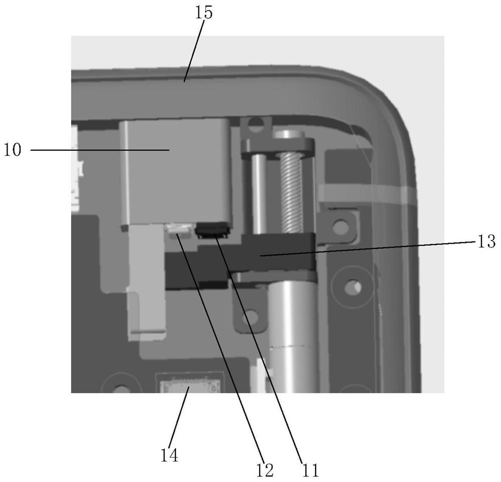
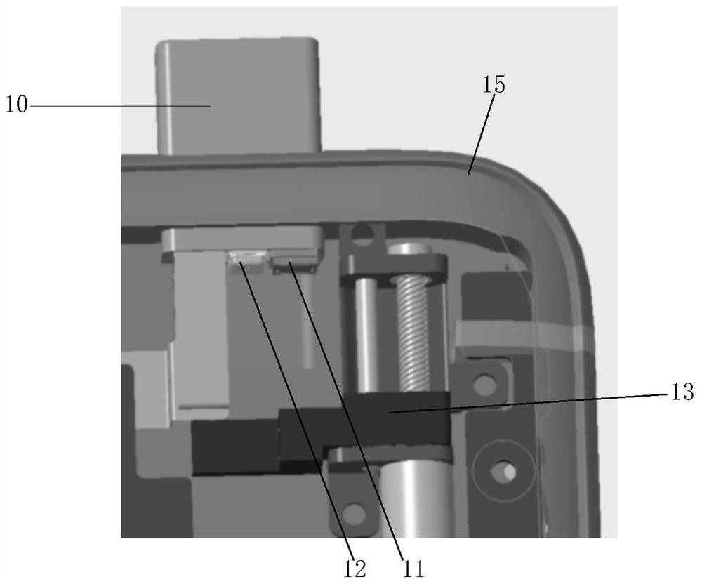
[0077] figure 1 It is a schematic structural diagram of an electronic device according to an exemplary embodiment. The electronic equipm...


PUM


Abstract

The invention provides electronic equipment and a detection method of a camera module, and belongs to the technical field of electronic equipment. The equipment comprises a lifting camera module, an ultrasonic transmitter, an ultrasonic receiver, a fixed seat, a processor and a machine body, the lifting camera module is arranged in the machine body, the ultrasonic transmitter and the ultrasonic receiver are both arranged at the bottom of the lifting camera module, and the lifting camera module, the ultrasonic transmitter and the ultrasonic receiver are all connected with the processor; the fixed seat is arranged in the machine body and is positioned below the lifting camera module; the ultrasonic transmitter is used for transmitting a first ultrasonic signal; the ultrasonic receiver is used for receiving the first ultrasonic signal and the second ultrasonic signal reflected by the fixed seat and transmitting the first ultrasonic signal and the second ultrasonic signal to the processor;and the processor is used for determining the current position of the lifting camera module according to the first ultrasonic signal and the second ultrasonic signal.

Description

technical field [0001] The present disclosure relates to the technical field of electronic equipment, and in particular, to a detection method for electronic equipment and a camera module. Background technique [0002] With the development of electronic devices such as mobile phones, full-screen electronic devices have become a trend in the development of the industry. However, due to the existence of the front-facing camera of the electronic device, the display space of the screen of the electronic device is occupied, which restricts the development of a larger screen-to-body ratio of the full screen. At present, in order to break through the limit of the screen-to-body ratio and realize a true full-screen electronic device, the front camera is made into a lifting camera, so as to solve this problem well. Since the lifting camera has a certain stroke, in order to accurately control the lifting of the lifting camera, it is necessary to detect the position of the lifting cam...

Claims


Application Information

Patent Timeline
Patent Type & Authority Applications(China)
IPC IPC(8): H04N17/00H04N5/225
CPCH04N17/002H04N23/50H04N23/57
Inventor 项吉
Owner BEIJING XIAOMI MOBILE SOFTWARE CO LTD
Why Eureka
Try Eureka