
Pump assembly, spraying system, mobile device and spraying method

A technology for spraying systems and pump components, which is applied to pump components, parts of pumping devices for elastic fluids, launch devices, etc., and can solve problems such as uncontrollable spray volume, waste of liquid medicine, and easy entry of air into pipes, etc.

Active Publication Date: 2020-12-29
SZ DJI TECH CO LTD
View PDF4 Cites 0 Cited by
  • Summary
  • Abstract
  • Description
  • Claims
  • Application Information

AI Technical Summary

Problems solved by technology

[0003] However, for pluggable water tanks, that is, water tanks that can be detached from mobile platforms such as drones, each time the water tank is plugged and unplugged, it is easy for air to enter the pipes of the sprinkler system.
When there is air in the pipeline of the sprinkler system, especially in the pump chamber, the outlet pressure of the sprinkler system is difficult to reach the above pressure threshold, so that the pressure relief valve cannot be pushed back to exhaust
At this time, it is necessary to manually open the pressure relief valve on each nozzle to discharge the gas in the spraying system, which not only takes time and effort, but also increases the labor cost; moreover, because it is difficult to judge when the exhaust is completed, it is usually necessary to wait for the liquid to be sprayed out Then close the pressure relief valve, the spray volume is uncontrollable, resulting in waste of liquid medicine

Method used


Image

  • Pump assembly, spraying system, mobile device and spraying method
  • Pump assembly, spraying system, mobile device and spraying method
  • Pump assembly, spraying system, mobile device and spraying method

Examples


Embodiment Construction

[0046] The following will clearly and completely describe the technical solutions in the embodiments of the present application with reference to the drawings in the embodiments of the present application. Obviously, the described embodiments are part of the embodiments of the present application, not all of them. Based on the embodiments in this application, all other embodiments obtained by persons of ordinary skill in the art without making creative efforts belong to the scope of protection of this application.

[0047] The flow charts shown in the drawings are just illustrations, and do not necessarily include all contents and operations / steps, nor must they be performed in the order described. For example, some operations / steps can be decomposed, combined or partly combined, so the actual order of execution may be changed according to the actual situation.

[0048] Some implementations of the present application will be described in detail below in conjunction with the ac...


PUM


Abstract

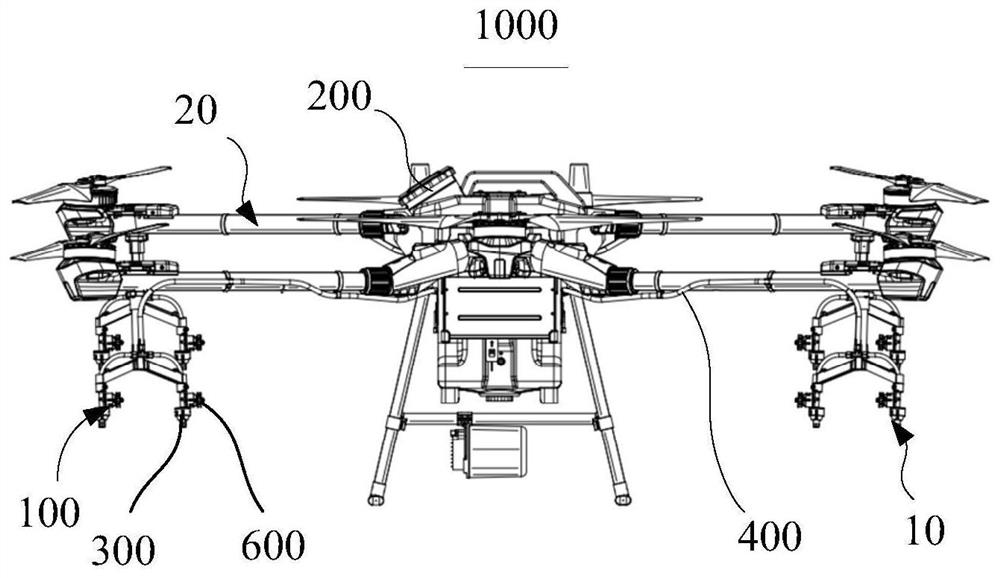
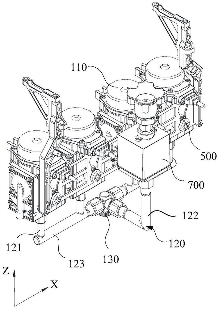
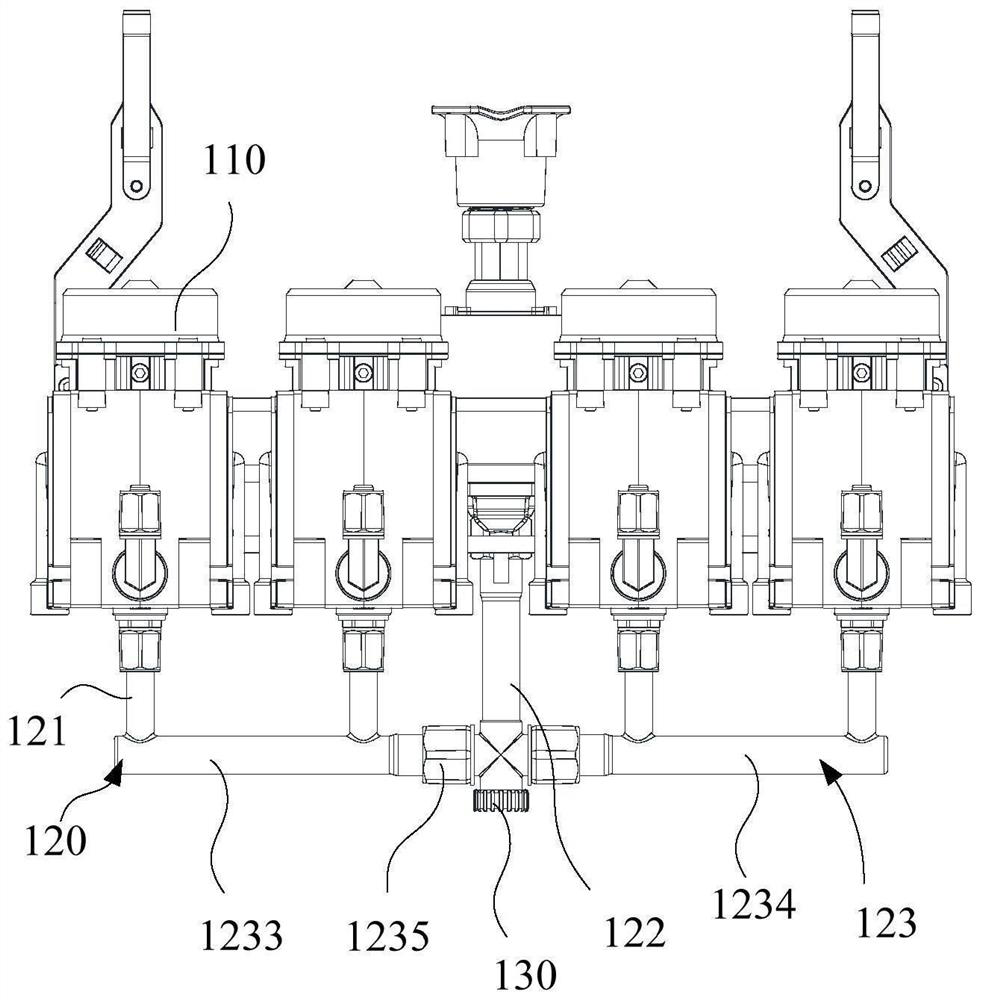
Disclosed are a pump assembly (100), a spraying system (10), a moving device (1000) and a spraying method. The pump assembly (100) includes water pump devices (110), liquid dispensers (120), and a pressure relief mechanism (130). Each liquid dispenser (120) includes a liquid outlet pipe (121) and at least one liquid inlet pipe (122) equal in number to each water pump device (110). One liquid inletpipe (122) is connected with a liquid supply tank (200) of the spraying system. Each liquid outlet pipe (121) is connected between each liquid inlet pipe (122) and each water pump device (110), and is used to guide liquid in each liquid supply tank (200) to the water pump device. Each liquid dispenser (120) is provided with a pressure relief port (140), and each pressure relief mechanism (130) isoperated to open or close each pressure relief port (140). When each pressure relief port (140) is opened, the gas in the pump assembly (100) can be discharged through each pressure relief port (140).The pump assembly can avoid waste of liquid medicine and reduce labor costs.

Description

technical field [0001] The present application relates to the technical field of pump assembly equipment, in particular to a pump assembly, a spraying system, a mobile device and a spraying method. Background technique [0002] With the continuous improvement of environmental protection requirements, people have higher and higher requirements for anti-leakage of spraying systems when spraying is stopped. Due to the effect of gravity, when the existing spraying system stops spraying, the spray head usually has a problem of liquid dripping, that is, there is a problem of dripping, which causes the waste of liquid medicine and pollutes the environment. In order to solve the problem of dripping from the nozzle after the spraying is stopped, a normally closed pressure switch, namely a pressure relief valve, is usually installed on the nozzle. When the outlet pressure of the spraying system is greater than the pressure threshold, the spraying system will start spraying. When the ...

Claims


Application Information

Patent Timeline
IPC IPC(8): A01M7/00F04B53/06A01G25/16A01G25/09B64D1/18B64C39/02
CPCA01M7/0042A01M7/005A01M7/0082A01M7/0089A01G25/09A01G25/16F04B53/06B64D1/18B64C39/02B64U2101/00
Inventor 舒展周乐周万仁
Owner SZ DJI TECH CO LTD
Learn More