
Anti-toppling and anti-theft flowerpot rack based on gravity irrigation

A flower pot stand and anti-falling technology, applied in the field of flower pot stands, can solve the problems of long watering time, damage, easy falling of flower pots, etc.

Inactive Publication Date: 2021-01-01
李兴雨
View PDF2 Cites 0 Cited by
  • Summary
  • Abstract
  • Description
  • Claims
  • Application Information

AI Technical Summary

Problems solved by technology

[0007] Aiming at the deficiencies of the prior art, the present invention provides an anti-falling and anti-theft flowerpot stand based on gravity watering, which solves the problem that the currently used flowerpot stands usually need to be watered manually, and when there are many flowerpot stands, watering needs to be spent. It takes a long time, and when the flower pot rack is placed outdoors or in the square, some uncivilized people will take the flower pots home privately due to the messy personnel, and the flower pots placed on the outdoor flower pot rack are easy to fall and cause damage The problem

Method used


Image

  • Anti-toppling and anti-theft flowerpot rack based on gravity irrigation
  • Anti-toppling and anti-theft flowerpot rack based on gravity irrigation
  • Anti-toppling and anti-theft flowerpot rack based on gravity irrigation

Examples


Embodiment 1

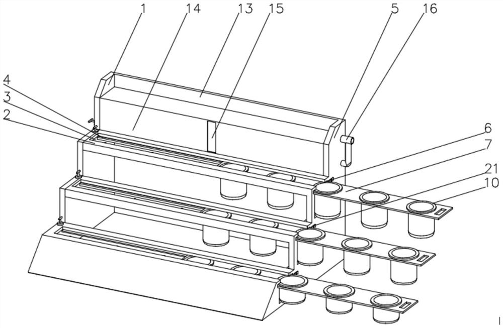
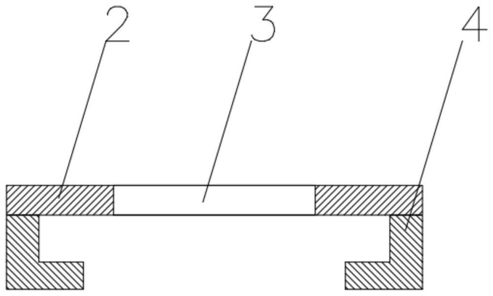
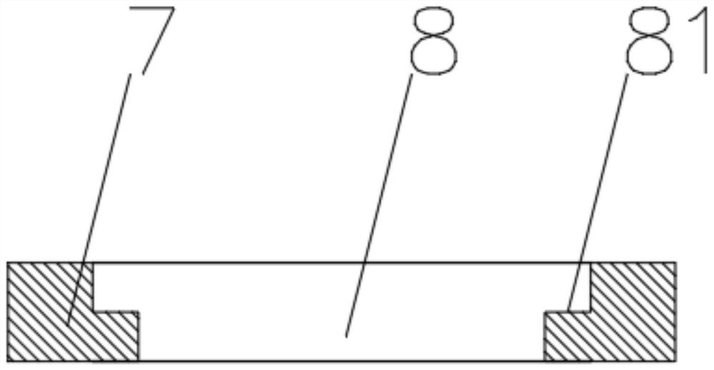
[0038] see Figure 1-6 , the present invention provides a technical solution: an anti-fall and anti-theft flower pot frame based on gravity watering, comprising a first stepped plate 1, one side of the first stepped plate 1 is fixedly connected with a fixed plate 2, and the top of the fixed plate 2 is provided with a matching The groove 3 and the bottom part of the fixed plate 2 located on both sides of the matching groove 3 are fixedly connected with the slideway 4, and the end of the fixed plate 2 away from the first stepped plate 1 is fixedly connected with the second stepped plate 5, and one side of the second stepped plate 5 A through hole 6 matching the matching groove 3 and the slideway 4 is provided, the inner wall of the slideway 5 is slidably connected with a support plate 7, the top of the support plate 7 is provided with a placement hole 8, and the inner wall of the placement hole 8 is slidably connected with a reducing ring 9 , the inner wall of the variable diame...

Embodiment 2

[0040] see Figure 1-8 On the basis of Embodiment 1, the present invention provides a technical solution: one side of the connecting plate 13 is fixedly connected with a water storage tank 14, and one side of the water storage tank 14 is provided with an observation window 15, and the water storage tank 14 is close to the second stepped plate One side of 5 communicates with a water inlet pipe 16, and the end of the water inlet pipe 16 away from the water storage tank 14 runs through the second stepped plate 5 and extends to the outside of the second stepped plate 5. The water storage tank 14 includes a water tank shell 141, and the top of the inner wall of the water tank shell 141 The main water tank 142 is fixedly connected, the bottom of one side of the main water tank 142 is connected with a water injection pipe 143, the water injection pipe 143 is provided with a first water valve 144, and the end of the water injection pipe 143 away from the main water tank 142 is connecte...


PUM


Abstract

The invention discloses an anti-toppling and anti-theft flowerpot rack based on gravity irrigation. The anti-toppling and anti-theft flowerpot rack comprises a first stepped plate, a fixing plate is fixedly connected to one side of the first stepped plate, a matching groove is formed in the top of the fixing plate, and sliding ways are fixedly connected to the portions, located at the two sides ofthe matching groove, of the bottom of the fixing plate; a second stepped plate is fixedly connected to the end, away from the first stepped plate, of the fixing plate, a through hole matched with thematching groove and the sliding ways is formed in one side of the second stepped plate, supporting plates are slidably connected to the inner walls of the sliding ways, a containing hole is formed inthe top of each supporting plate, and a reducing ring is slidably connected to the inner wall of each containing hole; and flowerpots are slidably connected to the inner walls of the reducing rings,and lock holes are formed in one sides of the supporting plates. The invention relates to the technical field of flowerpot racks. The anti-toppling and anti-theft flowerpot rack based on gravity irrigation is safe to use, good in stability, not prone to being stolen, convenient to water and capable of saving manpower and material resources.

Description

technical field [0001] The invention relates to the technical field of flowerpot racks, in particular to an anti-fall and anti-theft flowerpot rack based on gravity watering. Background technique [0002] In daily life, every major festival, we can often see a lot of flowers placed on the flowerpot racks in some squares in the city to create a beautiful atmosphere. These flowers placed in the squares are temporarily placed Yes, it will be transported away after the festival is over. [0003] According to the description in Chinese patent CN106108529A, it includes a frame, a movable box, a telescopic rod, a basin holder and a filter assembly, and the movable box is slidably installed in the inner cavity of the frame, and a lifting mechanism for driving the movable box to move up and down is provided in the frame. Mechanism; the telescopic rod is slidably installed in the inner cavity of the movable box, and a telescopic mechanism that drives the telescopic rod to move linear...

Claims


Application Information

Patent Timeline
IPC IPC(8): A01G9/02A01G27/00A01G27/02A01G13/00
CPCA01G9/023A01G13/00A01G27/003A01G27/02
Inventor 李兴雨
Owner 李兴雨
Features
  • Generate Ideas
  • Intellectual Property
  • Life Sciences
  • Materials
  • Tech Scout
  • Unparalleled Data Quality
  • Higher Quality Content
  • 60% Fewer Hallucinations
Learn More