
Mounting and pasting equipment based on manipulator

A manipulator and equipment technology, applied in the field of automatic mounting equipment, can solve the problems of low mounting speed, low labeling qualification rate, and the inability of grasping parts to rotate and lift at the same time, so as to save time and improve mounting efficiency. Effect

Pending Publication Date: 2021-01-01
广东奇创智能科技有限公司
View PDF0 Cites 4 Cited by
  • Summary
  • Abstract
  • Description
  • Claims
  • Application Information

AI Technical Summary

Problems solved by technology

[0004] The purpose of the present invention is to propose a mounting device based on a robot to solve the problem that the above-mentioned grasping parts cannot be rotated and lifted at the same time, resulting in low mounting speed and the inability to accurately control the mounting direction and the solution None of them have a visual inspection system, which leads to the problem of low labeling pass rate

Method used


Image

  • Mounting and pasting equipment based on manipulator
  • Mounting and pasting equipment based on manipulator
  • Mounting and pasting equipment based on manipulator

Examples


Embodiment Construction

[0046] Embodiments of the present invention are described in detail below, examples of which are shown in the drawings, wherein the same or similar reference numerals designate the same or similar elements or elements having the same or similar functions throughout. The embodiments described below by referring to the figures are exemplary only for explaining the present invention and should not be construed as limiting the present invention.

[0047]In describing the present invention, it should be understood that the terms "longitudinal", "transverse", "upper", "lower", "front", "rear", "left", "right", "vertical", " The orientation or positional relationship indicated by "bottom", "inner", "outer", etc. is based on the orientation or positional relationship shown in the drawings, which is only for the convenience of describing the present invention and simplifying the description, rather than indicating or implying the referred device or Elements must have certain orientatio...


PUM


Abstract

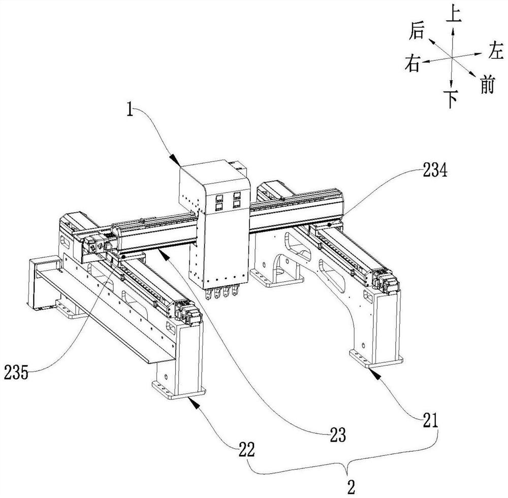
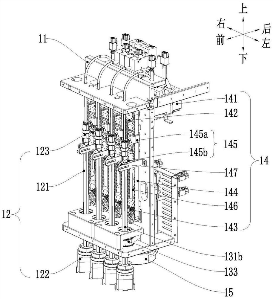
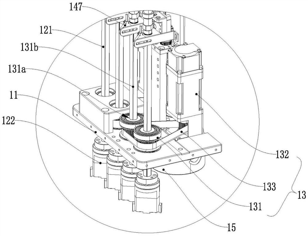
The invention discloses mounting and pasting equipment based on a manipulator. The mounting and pasting equipment comprises a labeling device and a rack, the labeling device comprises a fixing frame,a grabbing assembly, a rotating assembly, a lifting assembly and a visual detection assembly, the fixing frame is connected to the rack, the grabbing assembly comprises a grabbing rod and a grabbing piece, the grabbing rod is arranged on the front side of the fixing frame, the lower end of the grabbing rod penetrates out of the bottom of the fixing frame and is connected with the grabbing piece, the lifting assembly and the rotating assembly are connected to the fixing frame respectively, the lifting assembly is connected with the upper end of the grabbing rod, the visual detection assembly isarranged on the rear side of the fixing frame and electrically connected with the grabbing assembly and the rotating assembly, and the detection end of the visual detection assembly faces downwards.According to the mounting and pasting equipment, a driving gear is matched with a sliding groove of the grabbing rod through a limiting sliding rail so that the driving gear can drive the grabbing rodto rotate, meanwhile, the grabbing rod is slidably connected with the driving gear, and in the rotating process, the grabbing rod can rotate and stretch out of or retract into the fixing frame simultaneously.

Description

technical field [0001] The invention relates to the field of automatic mounting equipment, in particular to a robotic arm-based mounting equipment. Background technique [0002] Manipulators are increasingly being used in current industrial automation production. In the process of industrial production, the use of labels is widely used in factories. By marking the date, category, performance, etc. of products, automation equipment or workers can identify the corresponding status and product information through marking, and then The corresponding products are classified and sorted out for the next step of processing. [0003] At present, mounting equipment has appeared on the market, but in the current mounting manipulator, the grasping parts cannot be rotated and lifted at the same time, resulting in low mounting speed and inability to accurately control the mounting direction. Moreover, most of the equipment does not have a visual inspection system, and cannot judge and a...

Claims


Application Information

Patent Timeline
Patent Type & Authority Applications(China)
IPC IPC(8): B65C9/08B65C9/26B25J5/04B25J15/00B25J15/08
CPCB25J5/04B25J15/00B25J15/08B65C9/08B65C9/26
Inventor 万伟鑫喻卫杰余栋栋
Owner 广东奇创智能科技有限公司
Learn More